General Overview
A condenser water (CW) loop consists of a CW pump and motor, an evaporative cooling tower with a fan and motor, and a CW piping network. The CW loop system is designed to reject the heat given off by the condenser side of the chiller. A CW loop can have the following configurations:
Variable-speed Fans and Constant-flow System
A variable-speed constant-flow CW loop consists of variable-speed cooling tower fans and constant-speed CW pumps.
Variable-speed Fans and Variable-flow System
A variable-speed variable-flow CW loop consists of variable-speed CW pumps and a cooling tower with variable-speed fans.
Constant-speed Fans and Constant-flow System
A constant-speed constant-flow CW loop consists of constant-speed cooling tower fans and constant-speed CW pumps.
Components
The main components associated with the condenser water loop are shown in Figure 1.
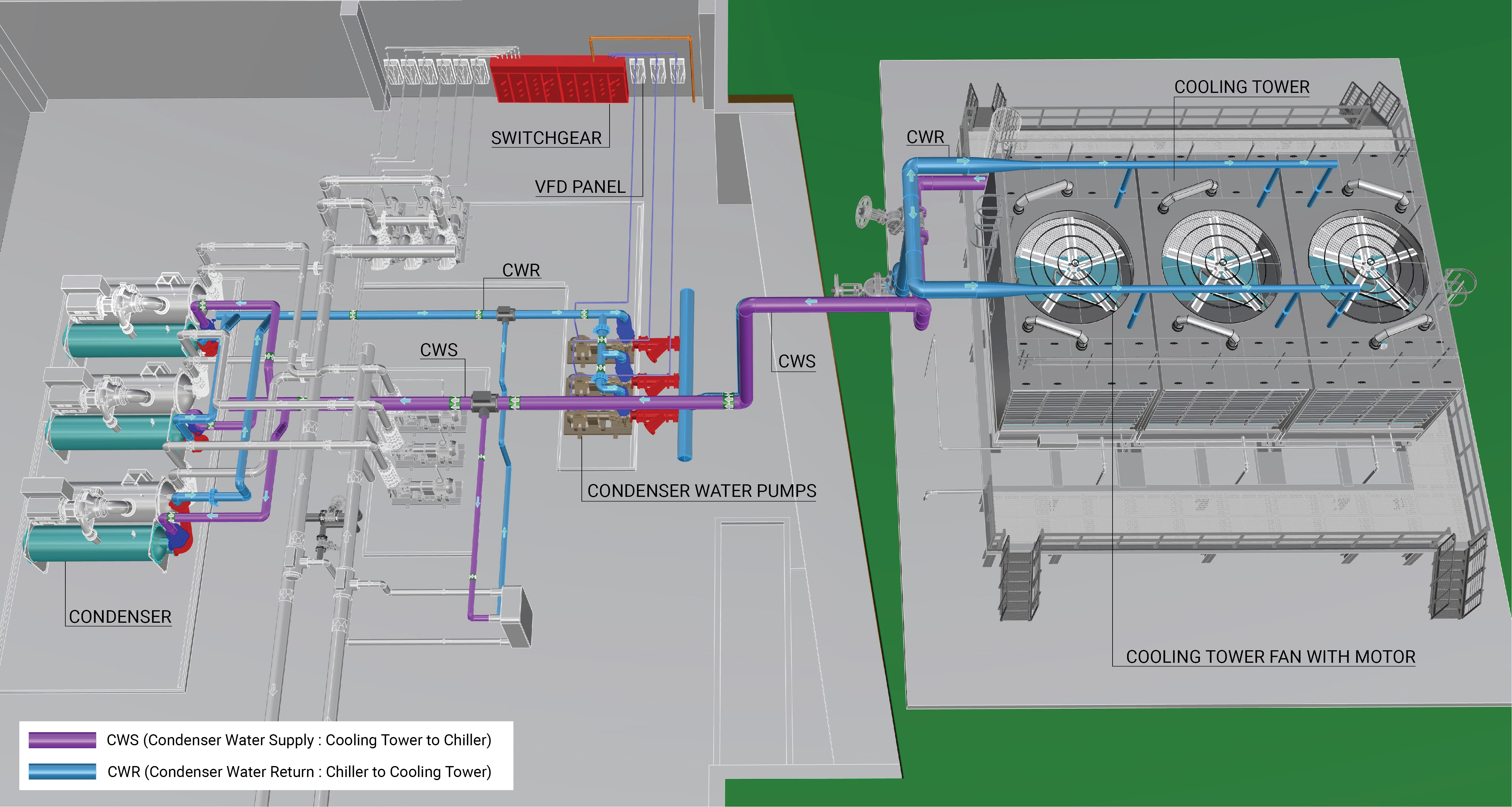
Condenser Water Pump and Motor
A condenser water pump and motor circulates condenser water from the condenser section of the chiller to the cooling tower. A condenser water loop pump and motor can be constant speed or equipped with variable frequency drives (VFDs).
Constant-speed, Constant-volume Pump
A constant-speed condenser water pump provides a fixed flow to the cooling tower and chiller, independent of cooling tower heat rejection capacity or building cooling load. Learn More
Variable-speed, Variable-volume Pump
A variable-speed condenser water pump and motor modulates the flow to the cooling tower and chiller based on the heat rejection capacity of the cooling tower and the minimum flow rate required through the condenser section of the chiller. Learn More
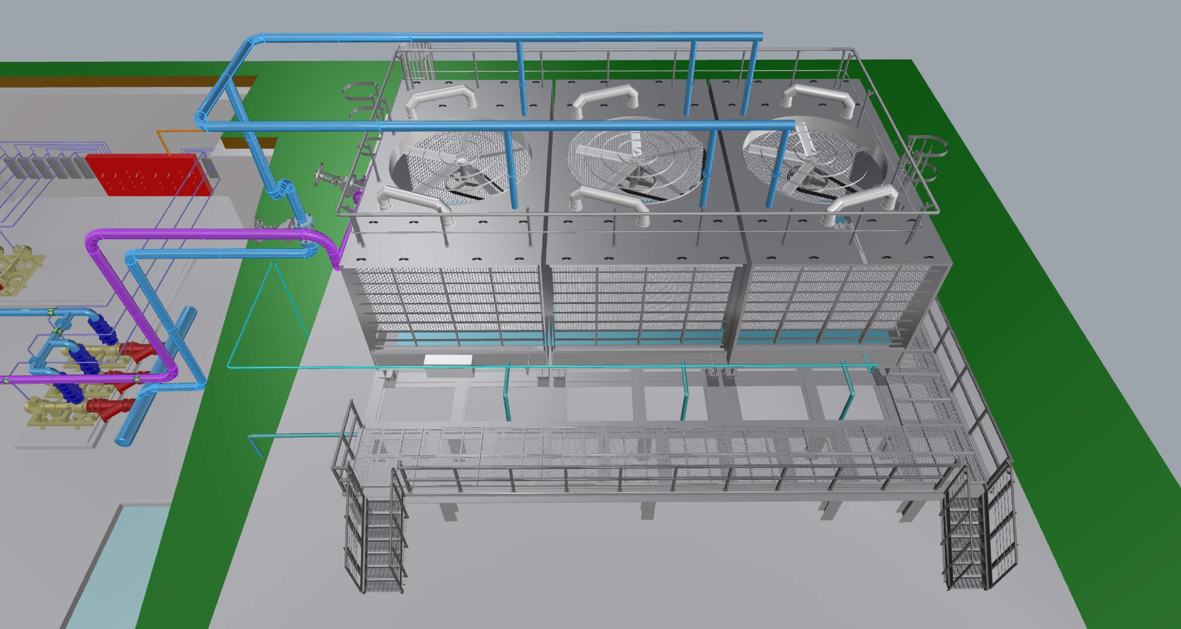
Evaporative Cooling Tower
An evaporative cooling tower rejects heat from the condenser section of the chiller, using forced airflow and the latent heat of evaporation to provide the cooling effect on the condenser water. A cooling tower may have one or more sections (called cells). Each cell typically has one fan and motor. The cooling tower fan and motor may operate at a constant or variable speed.
Constant-speed, Constant-volume Cooling Tower Fan
The overall cooling capacity of the condenser water loop in a cooling tower with multiple cells and constant speed fans and motors is controlled by staging (turning on) the cells. Learn More
Variable-speed, Variable-volume Cooling Tower Fan
Cooling towers with variable speed fans and motors generally operate the fans at the lowest speed possible and stage fans based on the overall CW heat rejection needed to satisfy the specific sequence of operation of the chilled water plant. Learn More
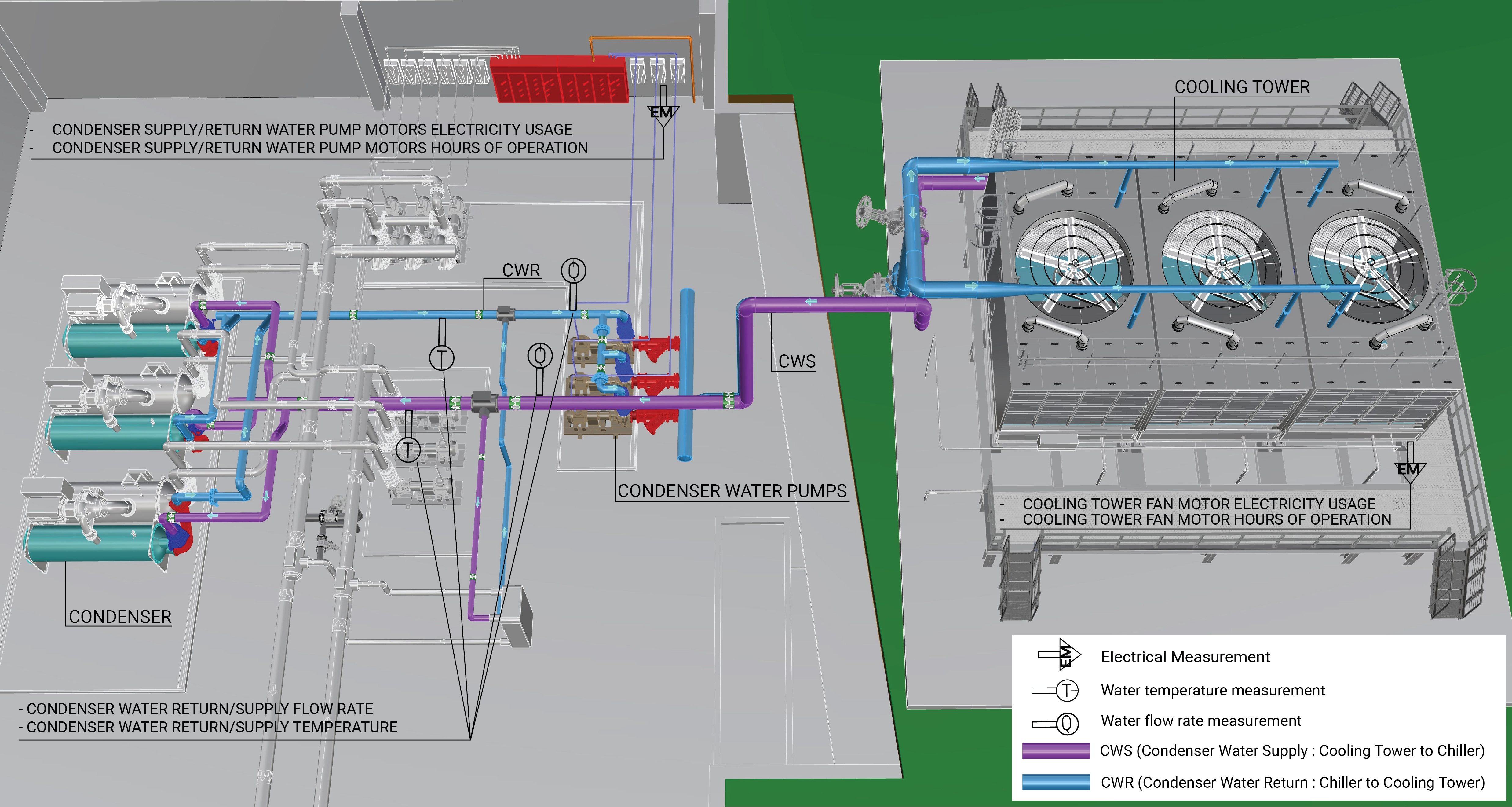
Evaluation of Energy Consumption
The primary energy consumption of a condenser water loop is the electricity used for the pump motors and the cooling tower fans. Table 1 provides a summary of system component measurements and value calculations needed to quantify the annual energy consumption and operating characteristics of a CW loop.
| System Quantification | Value to be Quantified | Energy Consuming Components | Measurements |
|---|---|---|---|
| CW Loop electricity usage (kWh) - variable-speed system |
|
Variable-speed pump motor | |
| Cooling tower electricity usage (kWh) - variable-speed system |
|
Variable-speed cooling tower fan motors | |
| CW Loop electricity usage (kWh) - constant-speed system |
|
Constant-speed pump motor | |
| Cooling tower electricity usage (kWh) - constant-speed system |
|
Constant-speed cooling tower fan motors | |
| Heat rejected to the outdoors |
|
Condenser |
Measurement Locations
The measurements for the condenser water loop are schematically shown in Figure 3, include:
Further Reading
-
ASHRAE (2020). “ASHRAE Handbook: HVAC Systems and Equipment,” Chapter 40. COOLING TOWERS. I-P Edition.
-
Taylor, S (2012). “Optimizing Design & Control of Chilled Water Plants Part 5: Optimized Control Sequences”. ASHRAE Journal, Vol. 54, No 6. American Society of Heating, Refrigerating and Air Conditioning Engineers; pp: 56-74.