General Overview
A variable speed fan and motor uses a power-driven rotating impeller to circulate air. Air flow rates fluctuate as required by the plant and system it serves. Outdoor air temperature (OAT) is an indirect variable driving fan speed (since heating and cooling loads are affected by OAT). The heating and cooling loads are affected by OAT. Axial and centrifugal fans with a variable speed drive are the most common type of variable speed fans used in buildings.
Table 1 shows the plant and system configurations that may contain variable-speed fans and motors and the most common respective controlling variables.
| Plant | System | Component | Controlling Variable |
|---|---|---|---|
| Air-cooled Chilled Water Plant | Air-cooled Chiller | Condenser Fan | Outdoor air temperature (F) |
| Water-cooled Chilled Water Plant | Cooling Tower | Cooling Tower Fan | Wet-bulb temperature (F) |
| Air Handling Plant | AHUs |
|
Outdoor air temperature (F) |
|
Boiler | Burner fan | Outdoor air temperature (F) |
Measurement Strategy
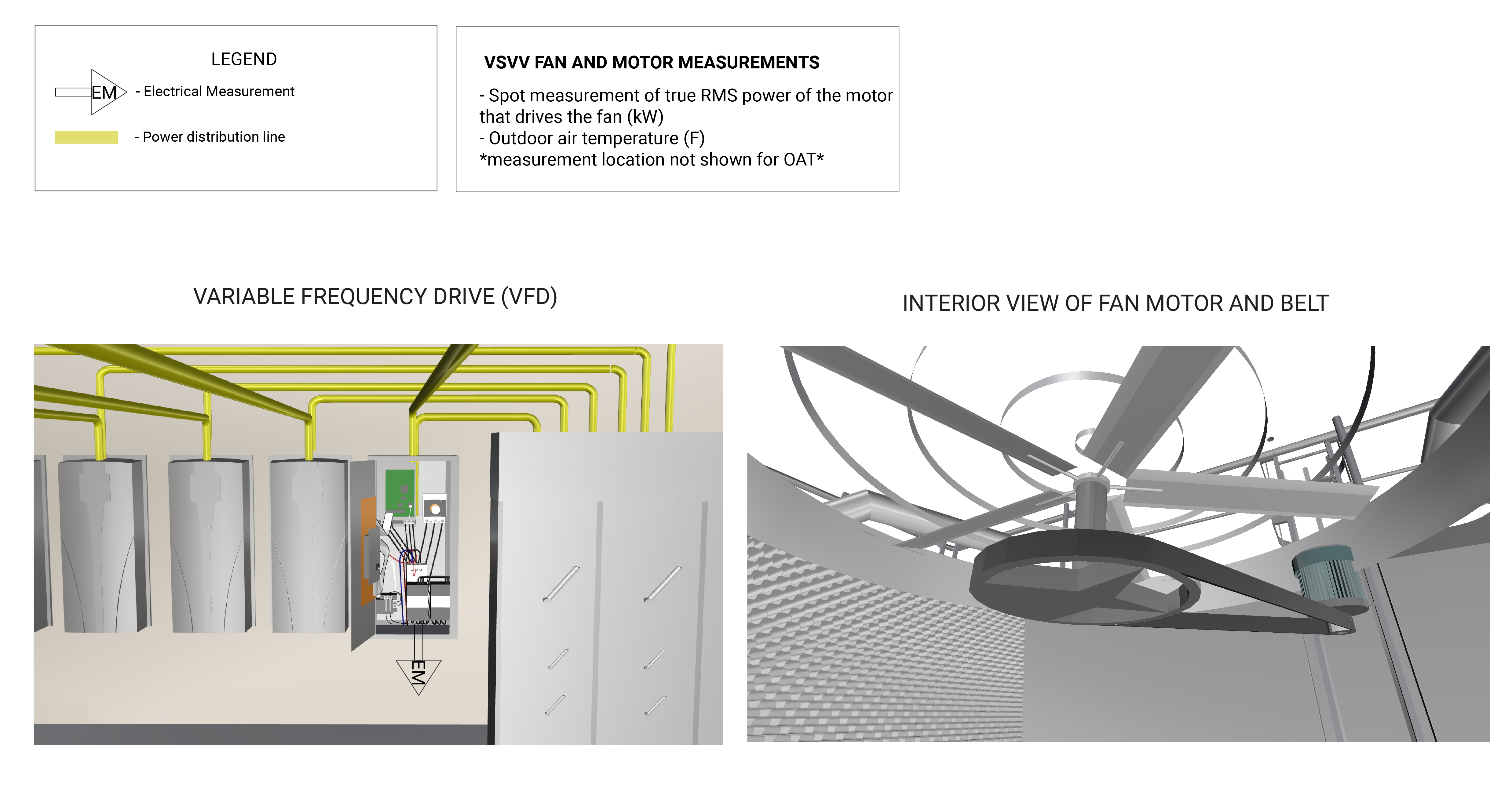
The measurement strategy for a variable-speed fan and its motor involves measuring power draw of the fan motor at various known speeds, developing a mathematical relationship between the power and speed, and then collecting average hourly motor speed and associated controlling variable (OAT, Wet-bulb temperature). Measurement locations are generically represented in Figure 1.
What and How to Measure
Perform the following measurements to quantify the energy consumption and operating characteristics of a VSVV fan and motor:
Measurement Equipment
If you are NYC agency personnel and you’re already familiar with the measurements above, the Field Equipment Lending Library has put together a kit wit all the equipment needed for measuring this component:
Fan and Motor (Variable-Speed) kit
Use this kit to assess the energy consumption (electricity usage) of a variable-speed, variable-volume fan and motor.
Energy Consumption Quantification
The primary energy source for a variable-speed fan is the electricity used to run the fan motor. The general methodology for quantifying the energy consumption of a variable-speed fan and motor is based on the true RMS power of the three-phase power supply, measured either at the motor’s main electrical panel or at the three-phase input to the VFD. To develop a temperature-dependent regression model, these values are regressed against a controlling variable, such as outdoor air temperature (OAT) or wet-bulb temperature. Depending on operational variability, daily or weekly models may be created to better characterize the component. This model is then used with climate normal year data to estimate the typical energy use of the variable-speed fan.
How to Quantify
The following downloadable file(s) can be used to calculate energy consumption based on the measurements taken for the specific type of VSVV fan and motor:
For VSVV AHU Supply/Return, Chiller Condenser, and Boiler Burner Fans
Variable Speed Fan Energy Using kW Data Calculator
Uses hourly true RMS power to calculate hourly energy consumption then estimate the annual energy consumption of a VSVV fan motor.
+More Info
This calculator can work with data from two fans, e.g., if you measured a supply and return fan in an AHU use this calculator to estimate the total annual energy consumption of the AHU. Data from both fans must be in the same format.
For VSVV Cooling Tower (CT) Fans
Further Reading
-
Boyd, BK.; McMordie Stoughton, KL.; Lewis, T. (2017). “Cooling Tower (Evaporative Cooling System) Measurement and Verification Protocol.” Golden, CO: National Renewable Energy Laboratory. https://www.nrel.gov/docs/fy18osti/70219.pdf.
-
Crowther, H.; Furlong, J. (2004). “Optimizing Chillers and Towers.” ASHRAE Journal, Vol. 46, No. 7; pp. 34-40.
-
Morrison, F. (2014). “Saving Energy with Cooling Towers.” ASHRAE Journal, Vol. 56, No. 2; pp. 34-40.
-
Tom, S. (July 2017). “CHILLED WATER SYSTEM OPTIMIZER.” Cat. No. 11-808-616-01. Farmington, Connecticut: Carrier Corporation.