General Overview
A chilled water (CHW) loop consists of two main components: pumps and motors, and a piping network. The pumps circulate chilled water from the chiller’s evaporator through the piping network to terminal units, such as water-to-air heat exchangers in air handling units or radiant equipment like chilled beams, before returning it to the chiller. A CHW loop can be designed as either a primary-flow system or a primary-secondary system.
Primary Flow
A primary-flow chilled water system consists of CHW pumps that circulate chilled water from the air-conditioned zone to the chillers. There are usually multiple pumps in the system to allow for staging and redundancy. These pumps often pump water into a single common pipe called a header, which allows them to run in parallel and service multiple chillers; however, some facilities have a single pump dedicated to each chiller. Primary-flow systems can be either constant-primary-flow or variable-primary-flow.
A constant-primary-flow system usually has a staged cooling system and constant speed CHW pumps.
A variable-primary-flow system has primary CHW pumps with variable speed drives that regulate the flow of the system based on the cooling load of the building.
Primary-secondary Flow
A primary-secondary chilled water system consists of a primary CHW loop with primary pumps as well as a secondary CHW loop with secondary pumps to distribute the cooling load to the building. The components of a primary-secondary flow system are shown in Figure 1. The following designs can be found in a primary-secondary flow system:
A constant-primary variable-secondary flow system uses constant-speed pumps to maintain flow through the primary loop, while separate pumps in the secondary loop distribute flow and cooling load to the facility. A primary-secondary chilled water system consists of a primary CHW loop with primary pumps, which circulates water through the chillers, and secondary CHW loop with secondary pumps which takes a portion of water from the primary loop and distributes it to the building.
A variable-primary variable-secondary flow system has variable frequency drives (VFDs) installed on primary and secondary pump motors controlled by the differential pressure in the piping network.
Components
The main components associated with the CHW loop are primary pumps for primary-flow systems and primary and secondary pumps for primary-secondary flow systems.
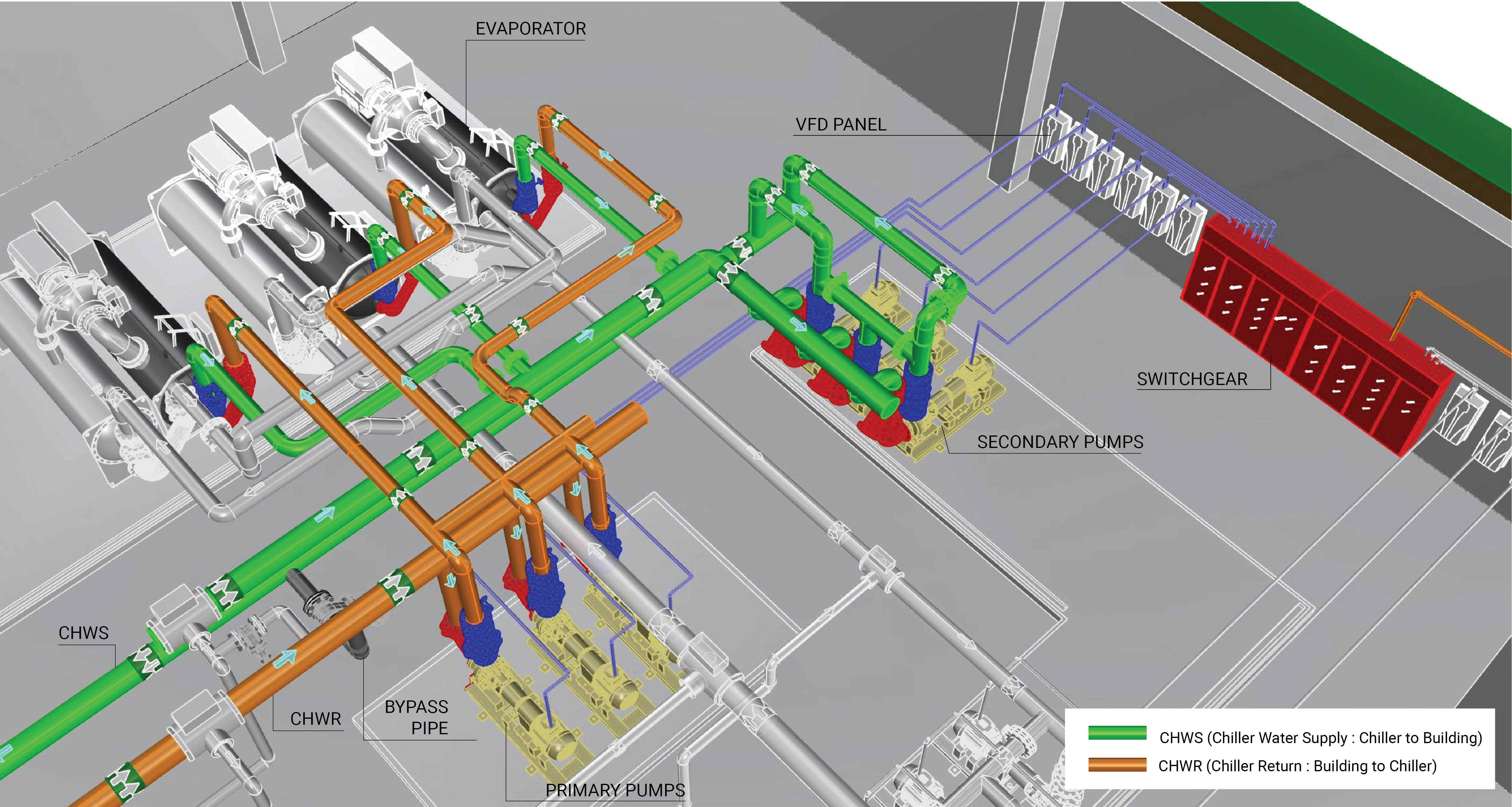
Primary CHW Piping Network
The primary CHW piping network is connected to the evaporator section of the chiller and extends through the building to deliver chilled water to that facility in a primary-flow system. In a primary-secondary system, the primary piping network is dedicated to circulating chilled water through the evaporator of the chiller.
Secondary CHW Piping Network
The secondary CHW piping network is connected to the primary piping network to deliver chilled water to the facility.
Primary CHW Pump and Motor
A primary CHW pump and motor circulates chilled water from the evaporator section of the chiller to the building in a primary-only system or to the secondary pump and motor through the piping network. A primary CHW pump and motor can operate at constant speed or variable speed based on the design of the chilled water plant.
Constant-speed, Constant-volume Pump
A constant-speed, constant-volume pump and motor operates at a single speed to circulate liquid (e.g., water, water, and glycol solution) through a piping network where the flow rate through the pump does not vary more than 5%. Learn More
Variable-speed, Variable-volume Pump
A variable-speed, variable-volume pump and motor circulate liquid (e.g., water or water and glycol solution) through a piping network where the flow rate fluctuates as required by the plant and systems they serve. Learn More
Secondary CHW Pump and Motor
A secondary CHW pump and motor circulates chilled water from the primary piping network to the building. A secondary CHW pump and motor are found in primary-secondary flow systems and can be at constant-speed or can be equipped with variable frequency drives that are controlled by the differential pressure in the secondary piping network.
Constant-speed, Constant-volume Pump
A constant-speed, constant-volume (CSCV) pump and motor operates at a single speed to circulate liquid (e.g., water, water, and glycol solution) through a piping network where the flow rate through the pump does not vary more than 5%. Learn More
Variable-speed, Variable-volume Pump
A variable-speed, variable-volume (VSVV) pump and motor circulate liquid (e.g., water or water and glycol solution) through a piping network where the flow rate fluctuates as required by the plant and systems they serve. Learn More
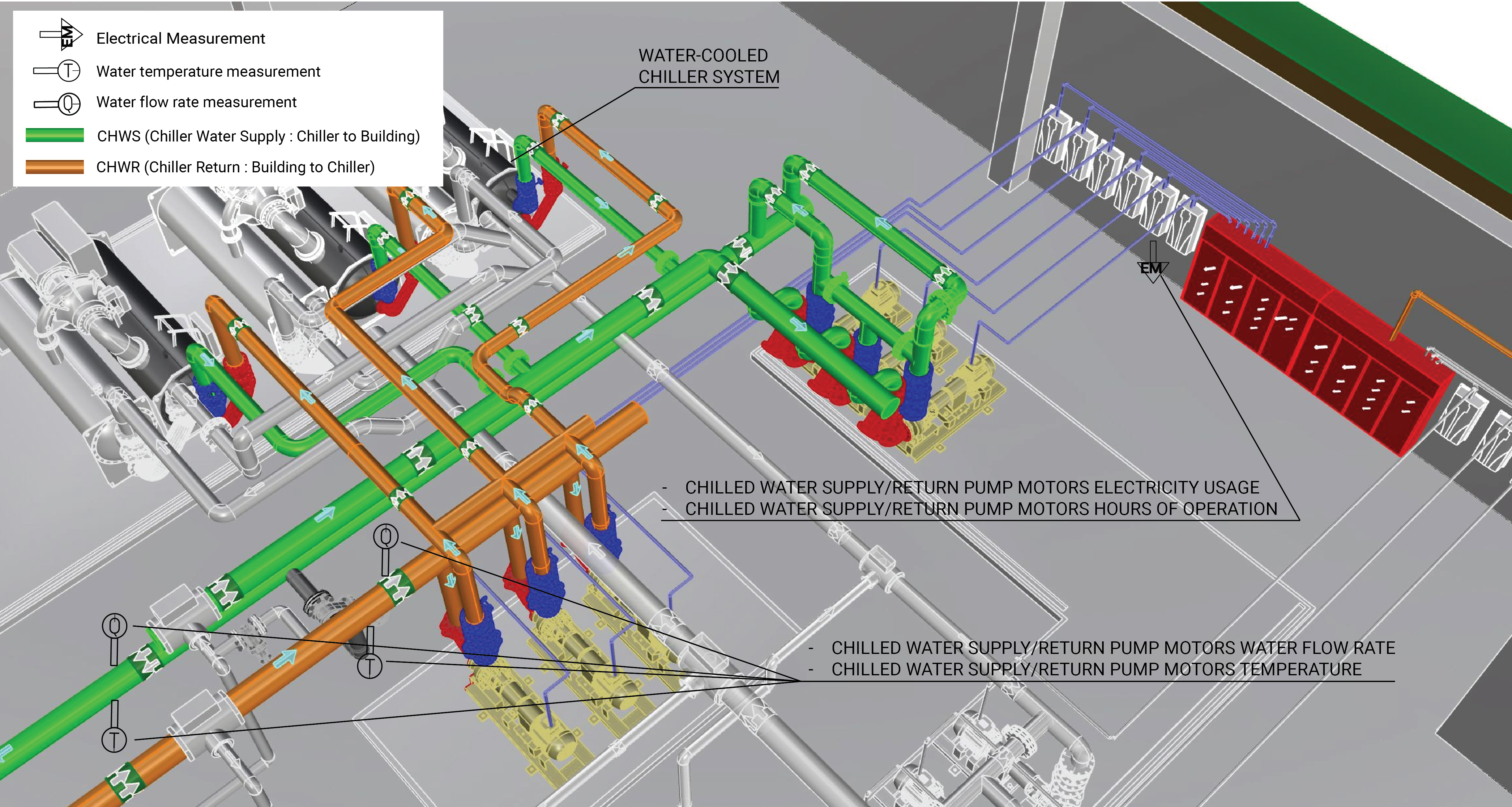
Evaluation of Energy Consumption
The primary energy consumption in a CHW loop is the electricity used to run the pump motors. The heat loss across the piping network contributes to the overall energy consumption for the entire chilled water plant.
Table 1 provides a summary of system component measurements and values needed to quantify the annual energy consumption and operating characteristics of a CHW loop.
| System Quantification | Values to be Quantified | Energy Consuming Component | Measurements |
|---|---|---|---|
| Primary CHW loop pump electricity usage (kWh) - constant-speed system |
|
Constant-speed pump motor | |
| Primary CHW loop pump electricity usage (kWh) - variable-speed system |
|
Variable-speed pump motor | |
| Secondary CHW loop pump electricity usage (kWh) - variable-speed system (if present) |
|
Variable-speed pump motor | |
| Cooling load on the building |
|
Evaporator |
Measurement Locations
The measurement locations for a primary-flow and a primary-secondary flow are shown in Figure 2.
Further Reading
-
ASHRAE (2019). “ASHRAE Handbook: HVAC Applications,” Chapter 43. SUPERVISORY CONTROL STRATEGIES AND OPTIMIZATION. I-P Edition.
-
Taylor, S (2012). “Optimizing Design & Control of Chilled Water Plants Part 5: Optimized Control Sequences”. ASHRAE Journal, Vol. 54, No 6. American Society of Heating, Refrigerating and Air Conditioning Engineers; pp: 56-74.