General Overview
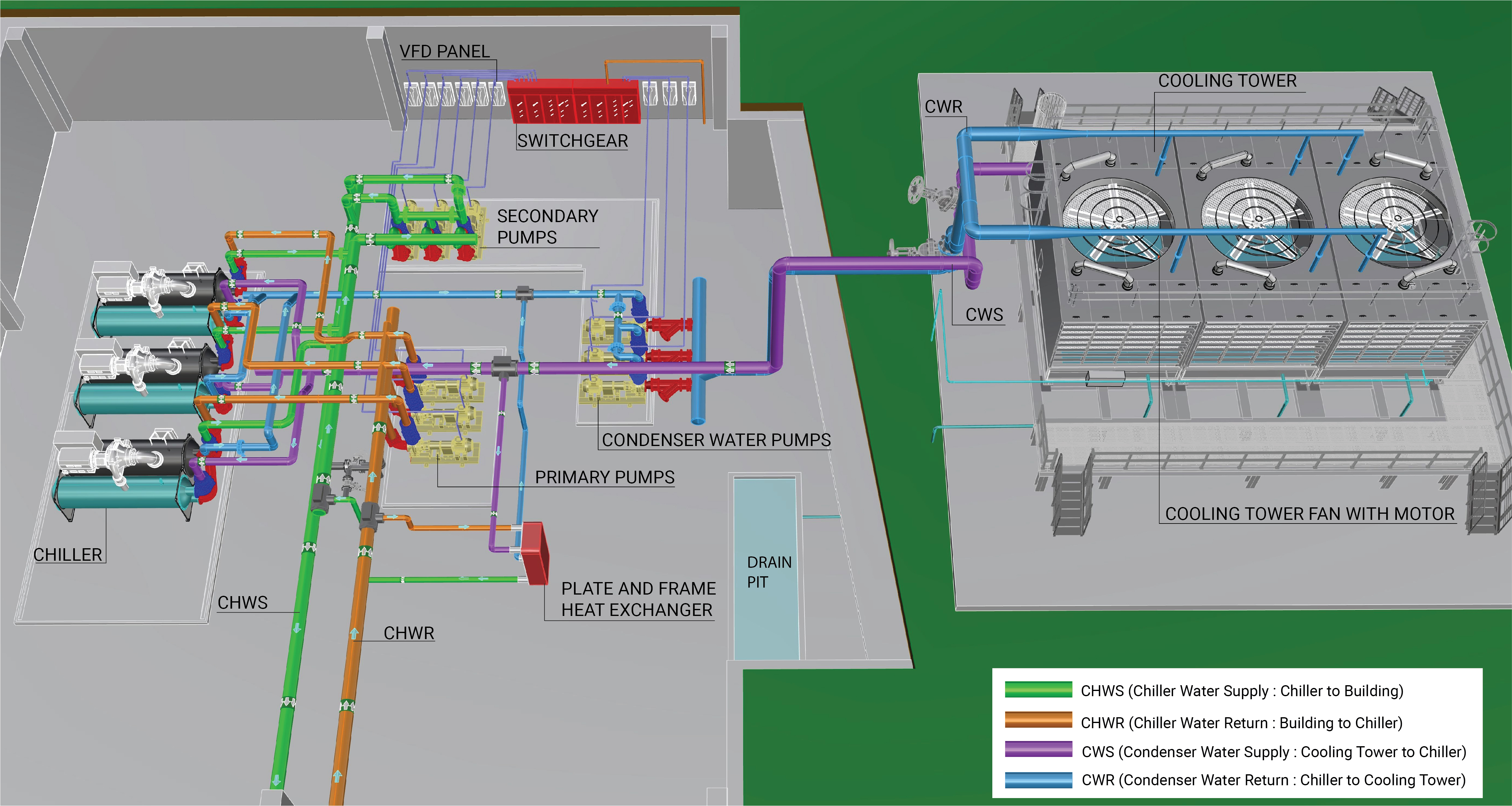
A water-cooled chilled water plant consists of a water-cooled chiller system, a condenser water loop system and a chilled water loop system operating together to meet cooling demand in a facility. If a waterside economizer is implemented in the facility, the chilled water plant includes a waterside economizer system as well.
Systems
Water-cooled Chiller
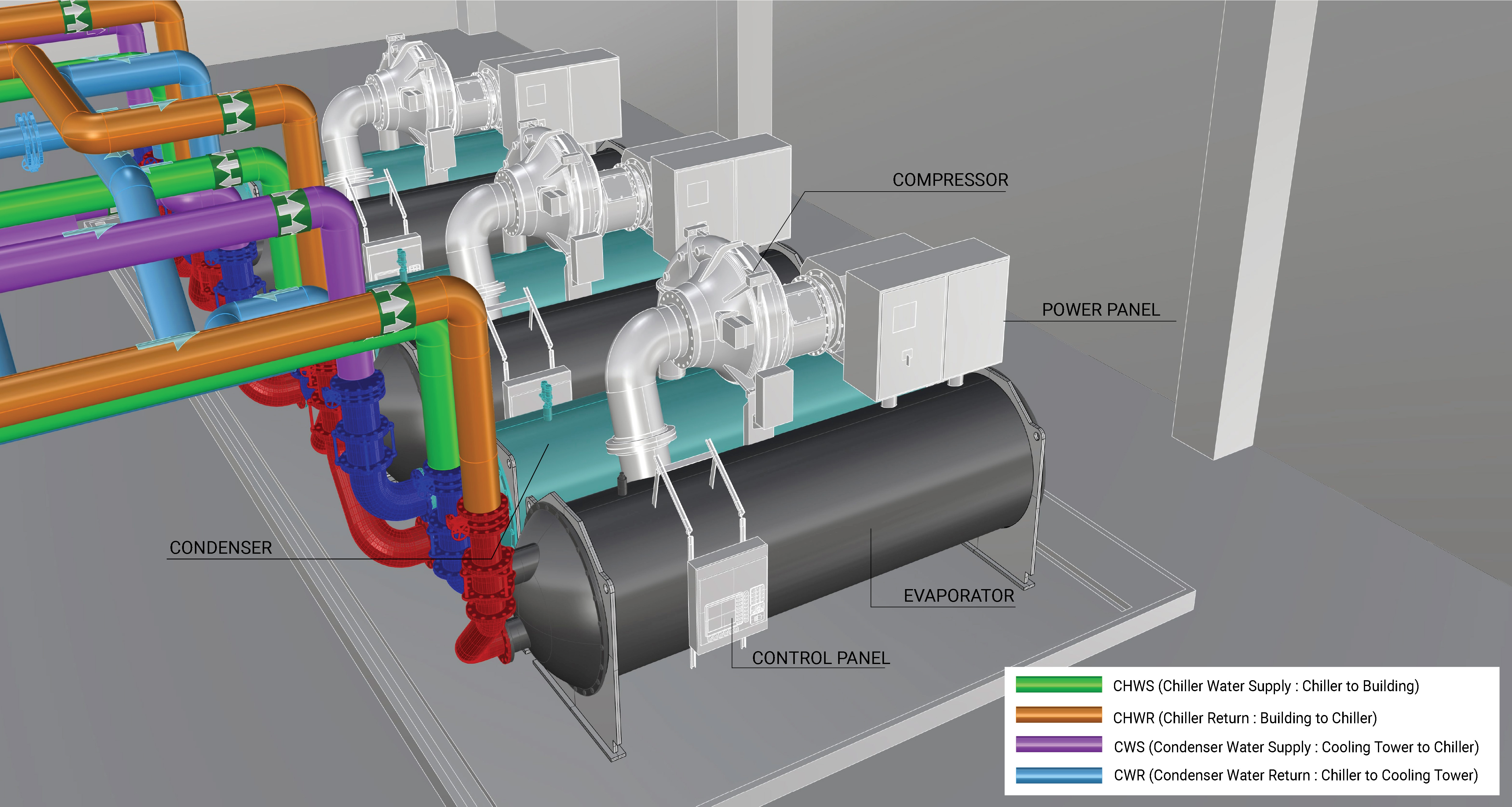
A water-cooled chiller produces chilled water using the basic refrigeration cycle, which is then distributed through the chilled water loop to the facility. The primary systems and components of a water-cooled chiller are shown in Figure 2. Learn More
Chilled Water Loop
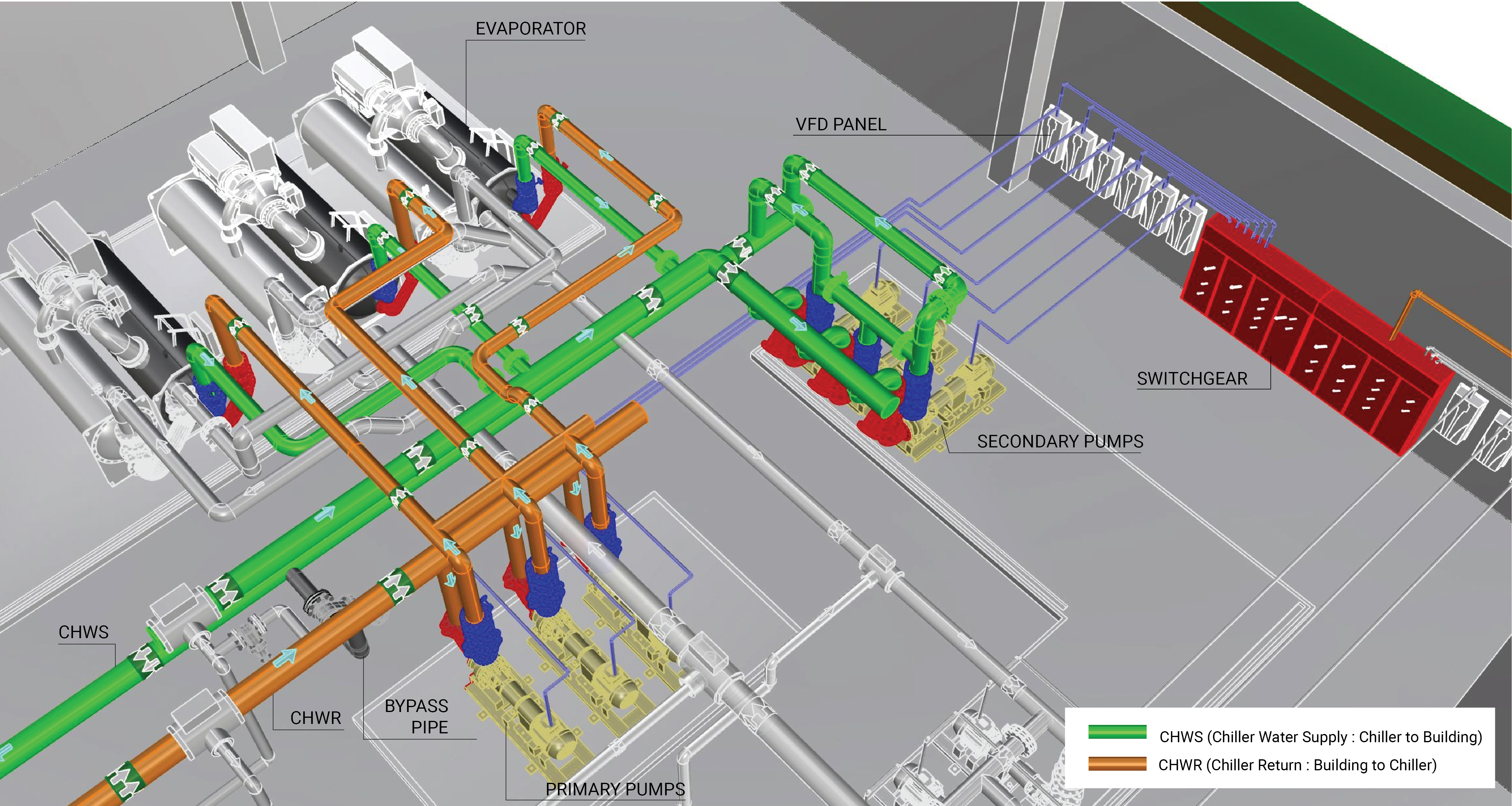
A chilled water loop consists of a closed loop distribution system that supplies chilled water to the building. Components of a chilled water loop are shown in Figure 3. Learn More
Condenser Water Loop
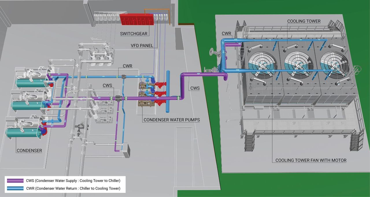
A condenser water loop consists of an open loop distribution system that circulates condenser water from a chiller condenser to a cooling tower, where the condenser water is cooled and returned to the chiller condenser. Components of a condenser water loop are shown in Figure 4. Learn More
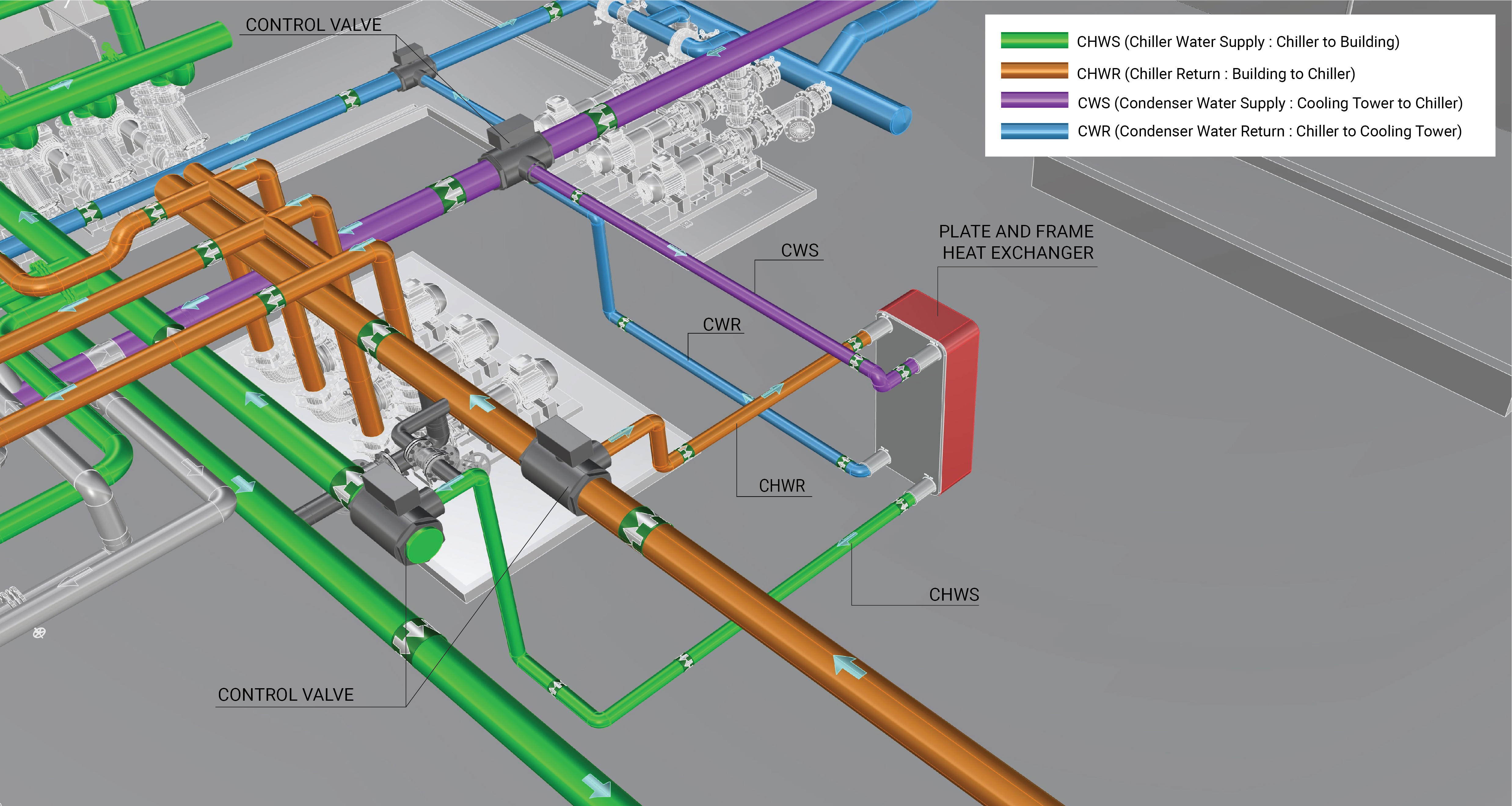
Waterside Economizer System
Waterside economizers may use an external plate-and-frame heat exchanger between the condenser and chilled water loop, or the chiller itself may be set up to perform the function of a waterside heat exchanger. When the outdoor temperatures are favorable, heat from the chilled water loop may be rejected directly to the condenser water loop through a heat exchanger without running the chiller compressor motor. Components of a waterside economizer system are shown in Figure 5. Learn More
Evaluation of Energy Consumption
The primary energy consumption of a water-cooled chilled water plant is the total energy used by its individual components. The thermal energy rejected from the building to the outdoors can also be measured to assess the plant’s overall performance, typically expressed in kilowatts of power consumed per ton of cooling provided (kW/ton). Table 1 summarizes the system component measurements and values needed to quantify the annual energy consumption and operating characteristics of the water-cooled chilled water plant.
| Plant Quantification | Values to be Quantified | Energy Consuming Component |
|---|---|---|
| Water-cooled chilled water plant electricity usage (kWh) |
|
|
| Cooling load on building/Heat rejected to the outdoors | Average hourly thermal load on chiller evaporator (Btu/h) | |
| Coefficient of Performance (COP) |
|
Further Reading
-
ASHRAE (2019). “ASHRAE Handbook: HVAC Applications,” Chapter 43. SUPERVISORY CONTROL STRATEGIES AND OPTIMIZATION. I-P Edition.
-
ASHRAE (2019). “ASHRAE Handbook: HVAC Applications,” Chapter 48. DESIGN AND APPLICATION OF CONTROLS. I-P Edition.
-
ASHRAE (2020). “ASHRAE Handbook: HVAC Systems and Equipment,” Chapter 38. COMPRESSORS. I-P Edition.
-
ASHRAE (2020). “ASHRAE Handbook: HVAC Systems and Equipment,” Chapter 40. COOLING TOWERS. I-P Edition.
-
Consulting Specifying Engineer (2021). “Understanding chilled water plant performance”. Consulting - Specifying Engineer | Understanding chilled water plant performance (csemag.com).
-
Taylor, S (2012). “Optimizing Design & Control of Chilled Water Plants Part 5: Optimized Control Sequences”. ASHRAE Journal, Vol. 54, No 6. American Society of Heating, Refrigerating and Air Conditioning Engineers; pp: 56-74.
-
Taylor, S (2014). “How to Design & Control Waterside Economizers.” ASHRAE Journal, Vol. 56, No 6. American Society of Heating, Refrigerating and Air Conditioning Engineers; pp: 30-36.