General Overview
The water-cooled chiller system produces chilled water through the basic refrigeration cycle and consists of an evaporator, a compressor, a condenser, and an expansion valve. The system can be constant-speed or variable-speed.
Constant-speed System
A constant-speed water-cooled chiller has a compressor motor that runs at a constant speed based on the total capacity of the chiller and adjusts the refrigerant flow with modulating vanes in the compressor when partial capacity of the chiller is needed.
Variable-speed System
A variable-speed water-cooled chiller has a variable frequency drive on the compressor motor and can reduce the speed of the compressor during partial load conditions.
Components
The four main components of every chiller are an evaporator, a compressor and motor, a condenser, and an expansion valve. The components are shown in Figure 1.
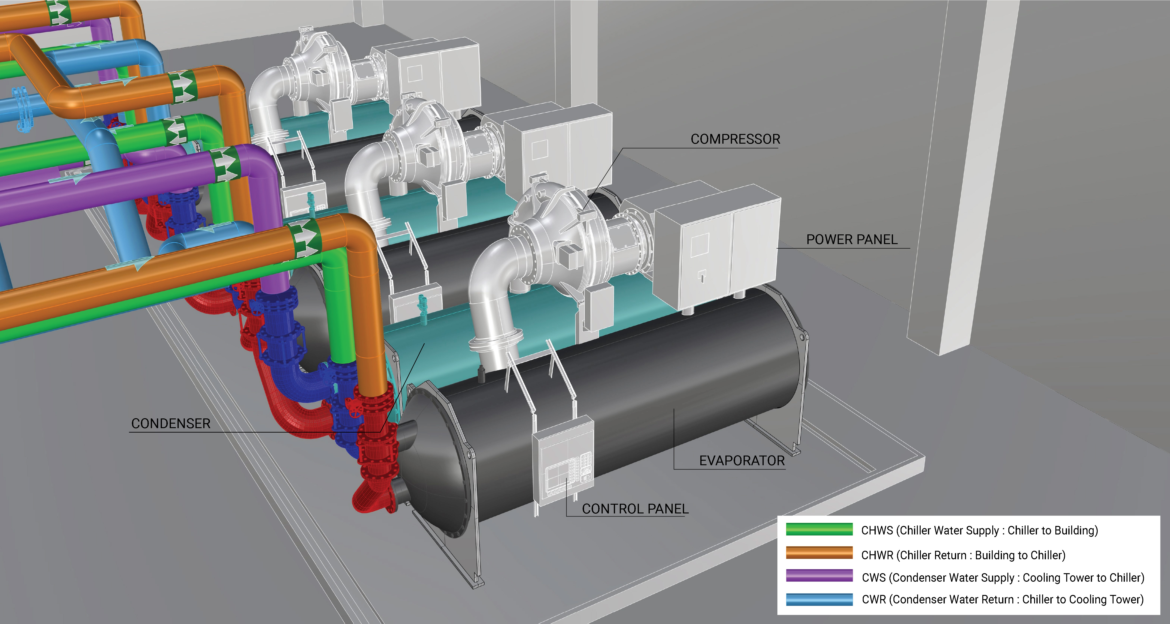
Evaporator
The evaporator transfers heat from the chilled water loop to the refrigerant through a heat exchanger.
Compressor
The compressor increases the temperature and pressure of the refrigerant between the evaporator and condenser sections of a chiller. A chiller may have one or more compressors.
Water-cooled chillers typically have centrifugal compressors. Centrifugal compressors are dynamic compressors, which increase refrigerant vapor pressure by converting the velocity pressure from the rotating impellers to static pressure in the discharged vapor. They can be driven with a constant-speed motor or a motor with a variable frequency drive (VFD).
A centrifugal compressor with a constant-speed motor uses variable guide vanes to change the speed of the gas as it enters the compressor, which changes the centrifugal force and the lift. “Lift” in a chiller system refers to the difference between the condenser water temperature leaving the chiller and the chilled water temperature leaving the chiller.
A centrifugal compressor with a VFD on the motor varies the speed of the impeller to control the lift.
Condenser
The condenser rejects heat from the refrigerant to the condenser water loop through a heat exchanger.
Expansion Valve
The expansion valve depressurizes the warm refrigerant between the condenser and evaporator to reduce the temperature of the refrigerant. Then, the cold refrigerant is delivered to the evaporator to pick up more heat from the chilled water loop.
Evaluation of Energy Consumption
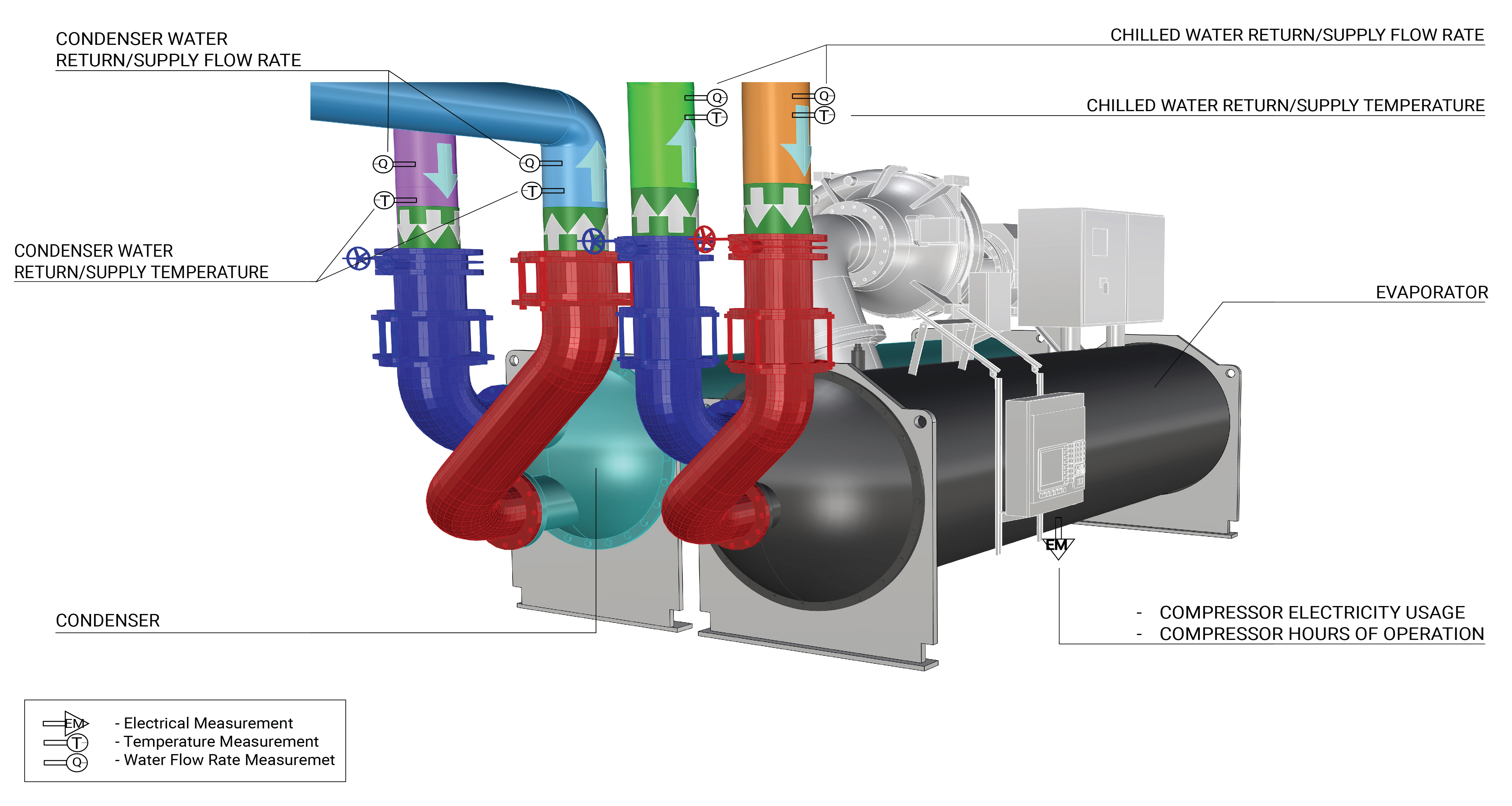
The primary energy consumption in a water-cooled chiller is the electricity used by the compressor motor and its controls. Thermal energy rejected by the chiller to the outdoors can be measured to evaluate the overall performance of the chiller, which can be expressed as kilowatts of power consumption per ton of cooling provided (kW/ton). Table 1 provides a summary of system component measurements and values needed to quantify the annual energy consumption and operating characteristics of a water-cooled chiller.
| System Quantification | Values to be Quantified | Component to be Measured | Measurements |
|---|---|---|---|
| Water cooled chiller electricity usage (kWh) - constant-speed system |
|
Constant-speed compressor motor and controls |
|
| Water cooled chiller electricity usage (kWh) - variable-speed system |
|
Variable-speed compressor motor and its controls |
|
| Cooling load on building |
|
Evaporator |
|
| Heat Rejected to the Outdoors |
|
Condenser |
|
Measurement Locations
The measurement locations for a water-cooled chiller are schematically shown in Figure 2.
Further Reading
-
ASHRAE (2020). “ASHRAE Handbook: HVAC Systems and Equipment,” Chapter 38. COMPRESSORS. I-P Edition.
-
Consulting Specifying Engineer (2021). “Understanding chilled water plant performance”. Consulting - Specifying Engineer | Understanding chilled water plant performance (csemag.com).