General Overview
A liquid-to-liquid heat exchanger transfers heat between two liquids using a temperature difference without direct contact between them.
In a building, this type of heat exchanger can be installed in condensate cooling, vent condensing, boiler blowdown, and waterside economizer (free cooling), and in refrigeration applications such as evaporators and condensers. Typical liquid-to-liquid heat exchangers are plate-and-frame heat exchangers and shell-and-tube heat exchangers.
Table 1 shows the plant and system configurations that may contain a liquid-to-liquid heat exchanger.
| Plant | System | Component | Controlling Variable |
|---|---|---|---|
| Water-cooled Chilled Water Plant | Waterside Economizer | Liquid-to-liquid heat exchanger | Outdoor air temperature (F) |
| Steam Plant |
|
Liquid-to-liquid heat exchanger | Blowdown water temperature (F) |
| Service Hot Water Plant | Service Hot Water Tank | Liquid-to-liquid heat exchanger | Schedule and occupancy |
Measurement Strategy
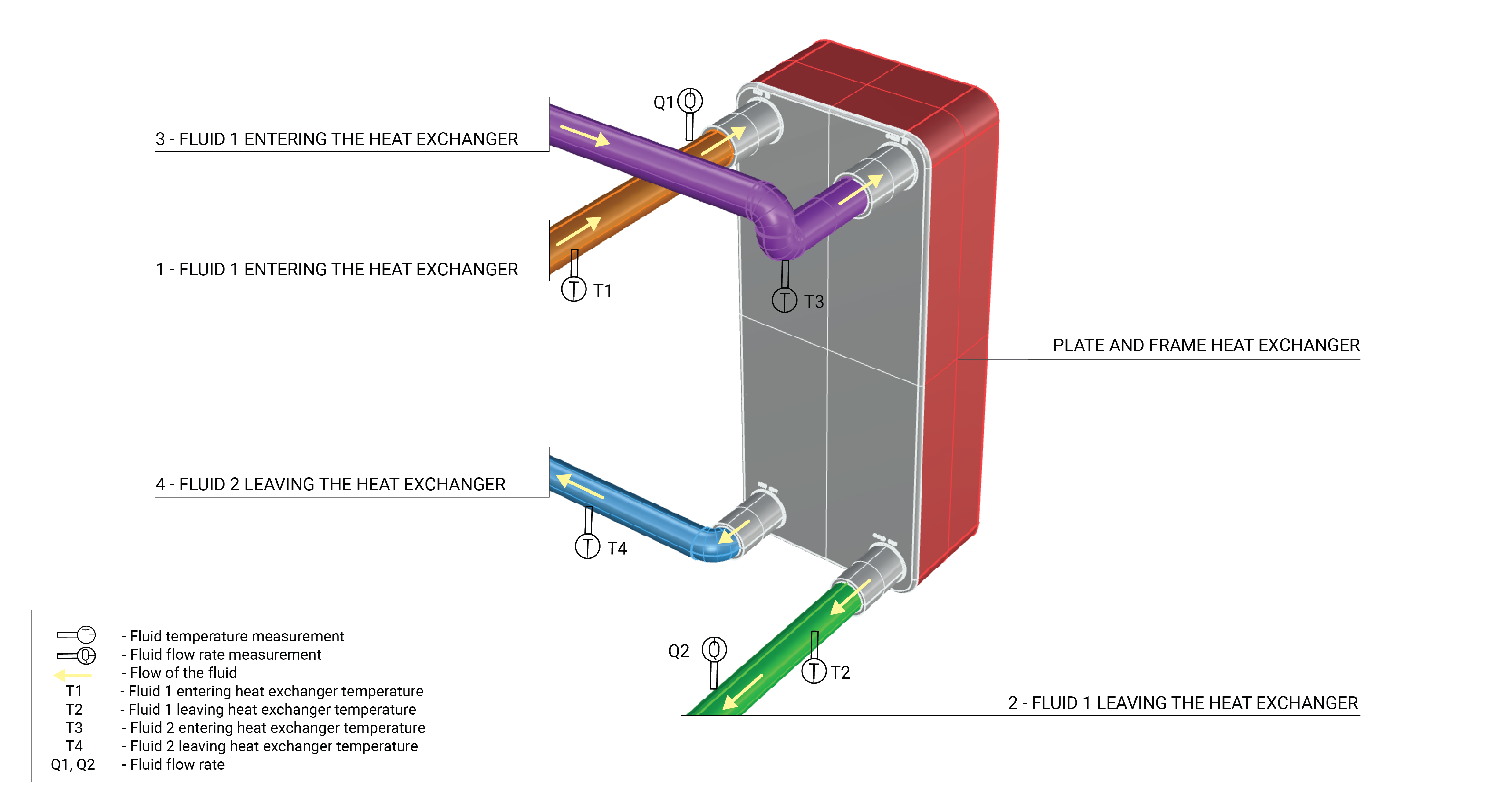
The measurement strategy for a liquid-to-liquid heat exchanger involves measuring the supply stream flow through the heat exchanger and the temperatures at the supply stream inlet and outlet. If a pump is used in the system, the flow rate can be measured at the supply stream pump. An example of the measurement locations are shown in figure 1.
What and How to Measure
Perform the following measurements to quantify the annual heat transfer and operating characteristics of a liquid-to-liquid heat exchanger:
If direct measurement of water flow rate is not possible, use the following measurement as proxy:
Measurement Equipment
If you are NYC agency personnel and you’re already familiar with the measurements above, the Field Equipment Lending Library has put together a kit wit all the equipment needed for measuring this component:
Liquid-to-Liquid Heat Exchanger kit
Use this kit to assess the heat transfer of a plate and frame liquid-to-liquid heat exchanger.
Energy Consumption Quantification
The general methodology for quantifying the useful energy supplied by a liquid-to-liquid heat exchanger is determined by the temperature differential and flow rate of the supply stream. These values are multiplied by the heat capacity and density of the liquid (e.g., water, water-glycol mix) to find the energy flow rate. The energy flow rate can be regressed against a controlling variable (such as outdoor air, pump runtime or flow rate) to develop a regression model. Depending on operational variability, daily or weekly models may be developed to better characterize the component.
How to Quantify
The following downloadable file(s) can be used to calculate energy consumption based on the measurements taken for this component:
Further Reading
-
Apogee Interactive (2022). “Free Cooling.” Commercial Library. https://c03.apogee.net/mvc/home/hes/land/el?utilityname=union-power&spc=cel&id=1094; accessed February 4, 2021.
-
ASHRAE (2019). ASHRAE Handbook: HVAC Applications. Chapter 48. DESIGN AND APPLICATION OF CONTROLS. I-P Edition.
-
ASHRAE (2020). ASHRAE Handbook: HVAC Systems and Equipment. Chapter 40. COOLING TOWERS. I-P Edition.
-
Carrier (2016). “How to Model a Waterside Economizer Application.” Carrier Engineering Newsletter, Vol. 4, Issue 1.
-
Gordon, J.M.; Ng, K.C. (2001). “Cool Thermodynamics: The Engineering and Physics of Predictive, Diagnostic and Optimization Methods for Cooling Systems,” Cambridge: Cambridge International Science Pub; pp. 159-177.
-
Trane (2008). “’Free’ Cooling Using Water Economizers.” Engineers Newsletter, Vol. 37-3. Also available at https://www.trane.com/Commercial/Uploads/PDF/11598/ News-%20Free%20Cooling%20using%20Water%20Economizers.pdf; accessed February 4, 2021.
-
Trane (2010). CDS-PRM001-EN. TRACE 700 User’s Manual-Building Energy and Economic Analysis, Version 6.2; pp. 43-49. Also available at https://tranecds.custhelp.com/ci/fattach/get/55941/0/filename/FreeCooling%5B1%5D.pdf; accessed June 17, 2022.
-
Taylor, S (2014). “How to Design & Control Waterside Economizers,” ASHRAE Journal, Vol. 56, No 6. American Society of Heating, Refrigerating and Air Conditioning Engineers; pp. 30-36.
-
Trane (2016). “Waterside Economizers - Keeping the ‘Free’ In Free-Cooling.” Engineers Newsletter, Vol. 45-2. Also available at https://www.trane.com/content/dam/Trane/Commercial/global/products-systems/education-training/engineers-newsletters/waterside-design/ADM-APN058-EN_06012016.pdf; accessed February 4, 2021.