Introduction
This calculation methodology is loosely based on the 2020 ASHRAE Handbook – Systems and Equipment, Chapter 26 for air-to-air heat exchangers. Part of the methodology described in Chapter 26 is applicable in liquid-to-liquid heat transfer systems, specifically about sensible heat. There is no latent heat transfer in liquid-to-liquid heat exchangers (no moisture control) only sensible heat transfer which can be measured by monitoring the liquid’s temperature. If the temperature of the liquids in the system changes as they flow through the heat exchanger, heat transfer is happening.
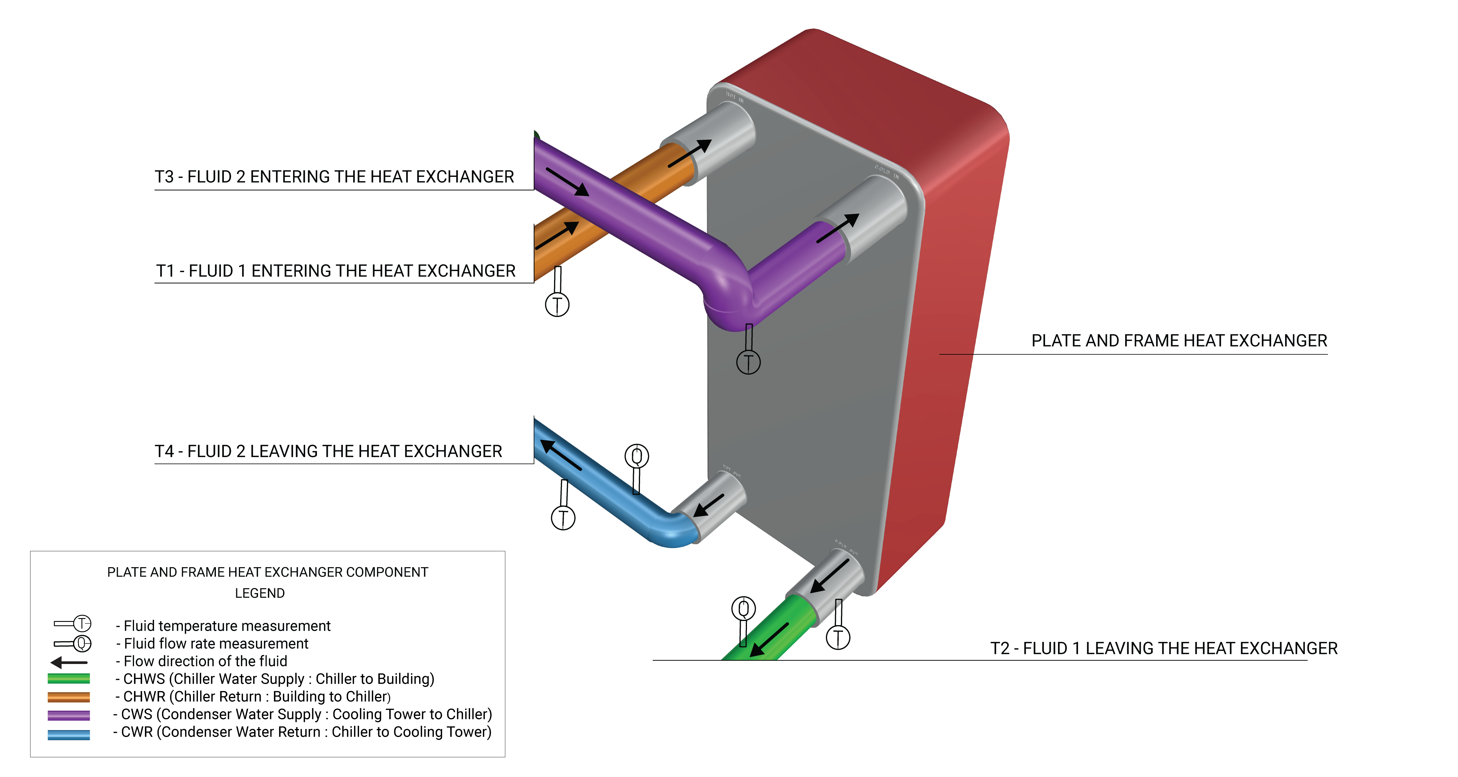
This methodology is applicable for systems that have liquid-to-liquid heat exchangers such as waterside economizers, blowdown heat recovery, and condensate cooling systems. Although this calculator can be used to evaluate energy transfer by any fluids (e.g., refrigerants), water is the only fluid to be evaluated in this methodology. Figure 1 shows an example of a plate and frame heat exchanger with the required measurement points.
Heat-transfer Calculation
This methodology works with hourly data only and each measurement is taken at the start of the hour. If the system operates seasonally, measurements should be taken for the duration of the season at one-hour intervals. If the system is not weather dependent, then a minimum of six (6) weeks of hourly data is required for this methodology to work.
Calculator
Measurements
The calculator relies on the measured data from the following measurement techniques:
Methodology
The following equations are used to calculate the sensible heat transferred by the heat exchanger for a full year. All data used in this section should be measured with data loggers per the measurements techniques above.
| Hourly Measured Values | |
|---|---|
|
|
Fluid Temperatures (F) |
|
|
Fluid 1: Water flow rate (GPM) |
|
|
Fluid 2: Water flow rate (GPM) |
- Calculate the mass flow rate of fluid 1 and fluid 2 leaving the heat exchanger for each hour interval.
Where,
Where,
- Heat transfer should be calculated only when the heat exchanger is operating. This can be determined by checking the temperature difference across the recovery system in both the supply side and waste heat stream side. Another condition is that water flow should exist across the heat exchanger.
Where,
Where,
Where,
- Calculate the sensible heat transferred by the heat exchanger for each hour interval.
Where,
Where,
- Calculate the total heat transfer by the heat exchanger for a whole year.
Where,
Further Reading
-
For general information on Option A M&V guides, please read section 4.2 (starts on page 23) of “M&V Guidelines: Measurement and Verification for Performance-Based Contracts Version 4.0” from the U.S. Department of Energy: https://www.energy.gov/sites/prod/files/2016/01/f28/mv_guide_4_0.pdf#page=23
-
ASHRAE (2020) “2020 ASHRAE Handbook-HVAC Systems and Equipment”