Understanding Electrical Spot Measurements
This technique uses a handheld power meter to take one-time measurements of various electrical properties such as true RMS power, voltage, current, and power factor. Measurements are taken at the electrical distribution systems such as the panel board, power panel or switchgear. One-time measurements provide a snapshot of power draw, voltage, current, and power factor for a system or component, such as lighting fixtures, chillers, and fan or pump motors. This technique is commonly used for loads with a constant power draw, including constant-speed fans, pumps, and certain lighting fixture systems.
Power meters use instantaneous measurements of current and voltage to calculate the instantaneous power draw. As the meter remains connected to the distribution system, it calculates the average power draw, which is displayed on the meter’s screen. Manufacturers of power meters and data loggers use different calculation methodologies to calculate the power draw. In order to compare power draw data obtained from different loggers and meters, refer to the user manual to understand the calculation methodology used by the equipment.
Electrical distribution systems can have different configurations, such as three-phase delta, three-phase wye, single-phase, and split phase on a delta configuration. It is important to first identify the configuration of the system before taking any measurements. The configuration of the system will determine the connections to make with the measurement equipment. Refer to the Measurement Steps section for more details on the different configurations.
Type of Measurement
This is a proxy measurement of electrical energy consumption of a system or component. Energy consumption is calculated with true RMS power draw and the runtime (operating schedule) of the system or component.
Measurement Equipment
The measurement equipment needed for this procedure is a handheld power meter with a current transformer and voltage cables. A power meter typically measures AC voltage, current, and power factor, and can display all values simultaneously.
The contents of this guide are largely based off the following equipment available in the Field Equipment Lending Library:
Clamp Meter equipment
Measures Power factor (PF), Reactive Power (VAR), Watt Hours (Wh), Kilowatt hours (kWh), AC Current, AC Voltage and more.
Power Quality Clamp Meter equipment
Measures Power factor (PF), Reactive Power (VAR), Watt Hours (Wh), Kilowatt hours (kWh), AC Current, AC Voltage and more.
While some power meters can measure true three-phase power by measuring each phase, other meters with fewer wire connections can only estimate three-phase power. The Fluke 345 PQ Clamp Meter is an example of a meter that only estimates three-phase power. The Extech PQ20711 is an example of a meter that can measure three phases without estimation. Both meters should only be used on a balanced load, meaning the currents and voltages on each phase are equal. If the load is not balanced, three-phase power cannot be accurately measured with a handheld meter and a data logger with the capacity to measure three phases at the same time (such as the Dent EliteProXC2) should be used instead.
Measurement Procedure
1. Prepare for Data Acquisition
The following sections discusses the most common wire configurations found in a distribution system and assume a handheld power meter is being used, for details on how to install data loggers refer to the True RMS Power measurement technique.
Values to measure:
- True RMS power (kW)
- Voltage (V)
- Current (Amps)
- Power Factor
2. Install Equipment
- Confirm that the equipment is operational.
- Identify whether the distribution system supplies electricity to other loads that are not relevant to the project (to avoid measuring unwanted loads).
- Identify the wiring configuration of the distribution system. This will determine how to set up the logger and sensors.
- Based on the wiring configuration and instructions from the equipment’s user manual, install the sensor and logger to measure the current, voltage, and power factor to the system.
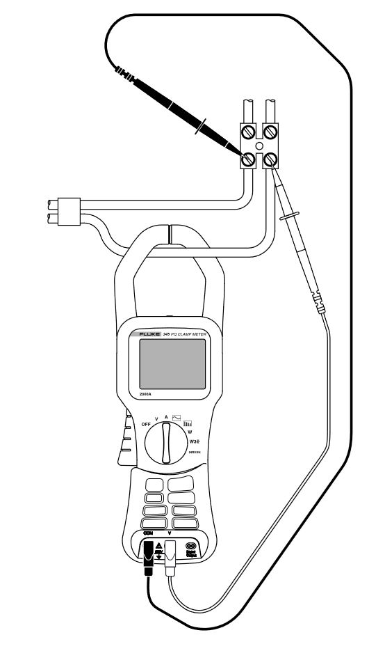
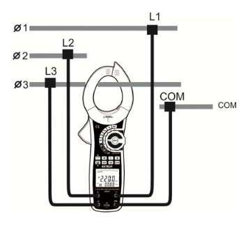
An example of how to connect the Fluke 345 PQ Clamp Meter is shown below:
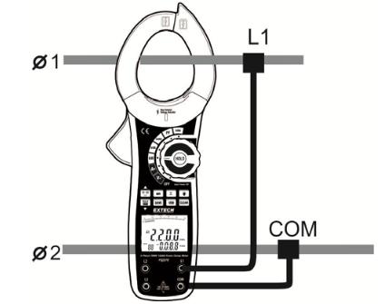
Single-phase Wire Configurations
A single-phase electrical distribution system typically consists of a hot wire and a neutral wire. The hot wire provides current to the load, while the neutral wire returns the current to the supply in order to complete the circuit. To measure the power draw of a single-phase system, measure the voltage across the hot wire and neutral wire, and measure the current of the hot wire. Figures 2 and 3 are examples of how measurement equipment offered by the FELL are connected on a single-phase system.
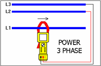
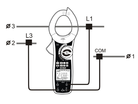
Three-phase Wire Configurations
For a three-phase distribution system, there are two common wire configurations: the three wire (delta) and four wire (wye). Both wire configurations require slightly different connections of the voltage leads. Manufacturers of power meters have specific instructions for making connections for a given wire configuration. Refer to the power meter’s user manual for detailed instructions. Figures 3, 4, and 5 are examples of how some of the meters offered by the FELL are connected to three-phase systems.
3. Process and Analyze Measured Data
Use the collected measurement data in the corresponding calculator file based on the type of component you are measuring:
Lighting
Fan and Motor
Pump and Motor
Compressor and Motor
Troubleshooting
This section provides some troubleshooting tips for the most common issues with equipment installation.
Unclear how power is distributed
It can be difficult or confusing to know how to connect a power meter to a panelboard because panelboards can have many different colored wires. Older panelboards might not have clear or accurate labeling at the circuit breakers, making it challenging to make proper connections.
In cases where it is unclear how the power is distributed, do not touch the panel or install any sensors without first having someone from the facility identify the power distribution.
The panelboard is too small, and connections cannot be made within the space constraints
Connect the sensors at the panelboard’s input or measure at the switchgear.
A voltage connection cannot be made because the alligator clips are too large or contact cannot be made with the metal lugs in the panelboard
Voltage connection can be difficult if you are not using the correct attachments. Voltage cables can have alligator clips or leads to accommodate for space constraints. In a case where connection cannot be made, use different size voltage leads or investigate alternative attachments for the panelboard’s configuration.
Unexpected negative values
At times, measurements will return as negative values because of how the voltage cables are connected. Connect voltage cables in different ways until you obtain positive values. Make sure the connections are correct for accurate power measurements. If you are not sure about the connections, consult a certified electrician.