General Overview
A constant-speed, constant-volume (CSCV) pump and motor operates at a single speed to circulate liquid (e.g., water, water, and glycol solution) through a piping network where the flow rate through the pump does not vary more than 5%. Centrifugal pumps are the most common type of pumps used.
Table 1 shows the plant and system configurations that may contain a CSCV pump and motor that operate based on a regular schedule (e.g., same time of day, same days of week).
| Plant | System | Component |
|---|---|---|
| Air-cooled chilled water plant | Chilled water loop | Primary chilled water pump |
| Water-cooled chilled water plant | Condenser water loop | Condenser water pump |
| Chilled water loop |
|
|
| Waterside economizer | Waterside economizer pump (if present) | |
| Hot water plant | Hot water boiler | Makeup water pump |
| Hot water loop | Building loop pump | |
| Steam plant | Steam boiler | Makeup water pump |
| Feedwater tank | Feedwater pump | |
| Service water plant | Service hot water loop |
|
Measurement Strategy
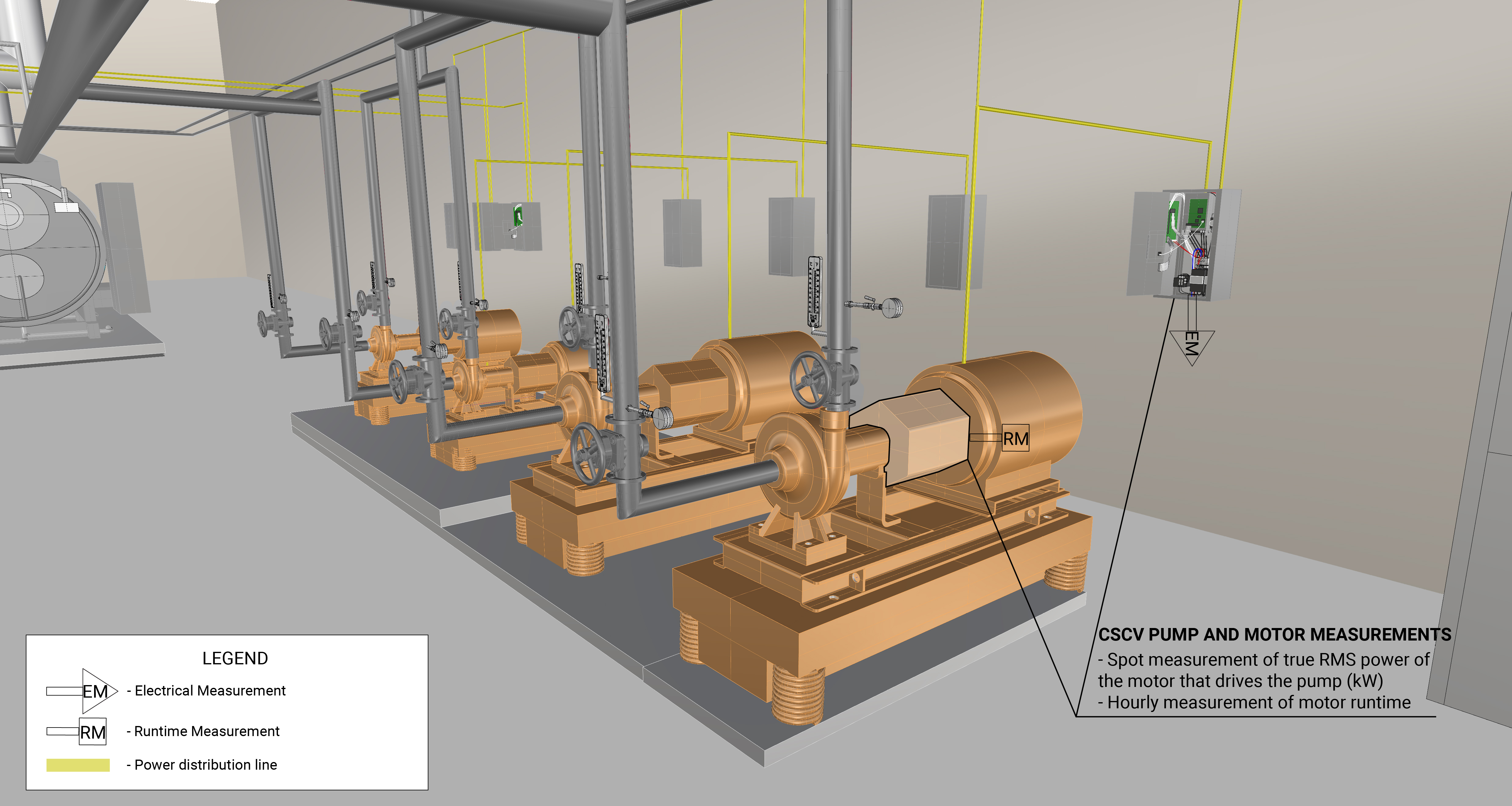
The measurement strategy for a CSCV pump and motor is to take multiple spot measurement of true RMS power and long-term hourly measurements of the operational schedule of the motor. The spot measurements of true RMS power will be averaged and the average value will be used to determine annual energy consumption. True RMS Power is measured at the mainfeed of the panelboard using a handheld power meter. A motor on/off logger is used to measure the hourly motor runtime. Measurement locations are generically represented in Figure 1.
What and How to Measure
Perform the following measurements to quantify the energy consumption and operating characteristics of a CSCV pump and motor:
Measurement Equipment
If you are NYC agency personnel and you’re already familiar with the measurements above, the Field Equipment Lending Library has put together a kit wit all the equipment needed for measuring this component:
Pump and Motor (Constant-Speed) kit
Use this kit to assess the energy consumption (electricity usage) of a constant-speed, constant-volume pump and motor.
Energy Consumption Quantification
The primary energy source for a CSCV pump is the electricity used to run the pump motor. Table 2 provides a summary of measurements needed to quantify the annual energy consumption and operating characteristics of the CSCV pump and motor.
How to Quantify
The following downloadable file(s) can be used to calculate energy consumption based on the measurements taken for all types of CSCV pump and motor:
Further Reading
-
Evans , P. (2017, Sept 26). How a Chiller, Cooling Tower and Air Handling Unit work together. Retrieved from The Engineering Mindset.com: https://theengineeringmindset.com/chiller-cooling-tower-air-handling-unit-work-together/
-
Evans, P. (2023, Jan 6). How Do Centrifugal Pumps Work. Retrieved from The Engineering Mindset.com: https://theengineeringmindset.com/how-do-centrifugal-pumps-work/