General Overview
When outdoor weather is relatively mild and there is still a need for cooling in a facility, waterside economizing in a central cooling plant can be implemented through a heat exchanger and a specific sequence of operation (SOO). Waterside-economizing in a water-cooled chilled water plant reduces chiller energy consumption when outdoor air temperature (OAT) and humidity conditions are suitable.
While waterside economizers are implemented in a variety of ways this guidance is specifically for indirect economizing by an auxiliary heat exchanger as a system retrofit. Direct economizing by the interconnection of water circuits between the chilled water loop and condenser water loop has proven to be problematic given the debris and contaminants that can be introduced into an open cooling tower.
Waterside economizers provide a cost-effective and energy-saving opportunity for a facility using a water-cooled chiller connected to an open cooling tower system and a liquid-to-liquid heat exchanger. When OAT is cold enough to use the cooling tower to chill the condenser water return temperature below the chilled water supply temperature setpoint, the chiller compressor can be turned off to achieve free cooling. Typically, the waterside economizer is turned on if the wet bulb temperature is below 45°F and the dry bulb is below 55°F. Under these conditions, a chilled water setpoint of around 55°F is achievable.
Waterside economizers can be installed in a chilled water plant with variable or constant speed pumping, though variable speed pumping provides greater savings. While airside economizers on the air handling units (AHUs) are preferred over waterside chilled water economizers due to their higher efficiency, there are certain conditions when waterside economizers are suitable. A multi-story office building that, for architectural reasons, does not allow for outdoor air intake for the AHUs is a candidate for waterside economizing. Buildings with a winter cooling load, such as a data center or museum, are also candidates for waterside economizers. Facilities where concerns about pollutants and humidity are introduced through the outdoor air intake of an airside economizer, such as a laboratory or educational building, are other applications.
Basic Control Logic
SOOs are essentially feedback loops that employ a combination of sensors, controllers, and actuators to impact a process and maintain a desired state. For example, a thermostat in a room sends a signal when the temperature falls below a certain setpoint, and the boiler system controls a pump to circulate hot water to the radiator to increase the temperature in the space. If the water temperature in the boiler is below a certain setpoint, the controls initiate the firing sequence for the boiler, and it continues to run until the boiler high temperature setpoint is reached.
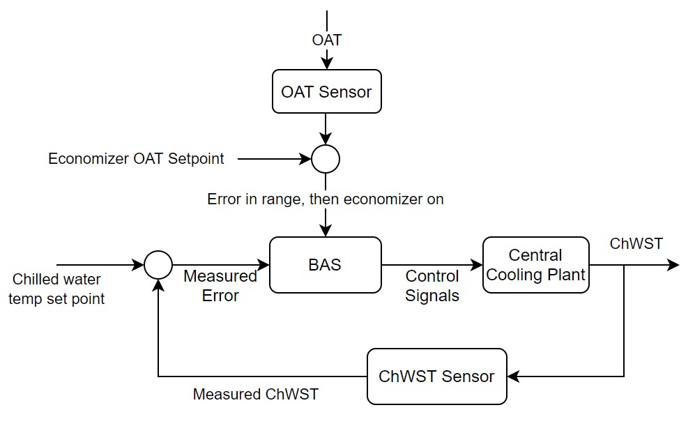
Figure 1 presents a schematic of the general principle of the waterside economizing control feedback loop. If the OAT is within the economizing range (when the dry bulb temperature is less than 55°F and the wet bulb temperature is less than 45°F), the economizer algorithm is turned on to alter the operation of the central cooling plant. The feedback loop with the chilled water supply temperature operates as normal to ensure the central cooling plant meets the cooling load. However, within the central cooling plant, a three-way valve directs the chilled water loop to bypass the chiller and go through a heat exchanger with the condenser water loop. This redirection essentially removes the refrigeration cycle from the heat transfer process. While the compressor is turned off to save energy, the cooling tower fans, condenser and chilled water pumps are still on.
Above the economizing temperature threshold, the three-way valve may partially direct the chilled water through the heat exchanger with the rest continuing to the chiller. In this case, the chiller compressor continues to run to share the load with the economizer.
Algorithm for the Sequence of Operation
This section describes the control algorithm to determine when economizing is turned on and off, and whether the economizing mode is full-load or partial-load. Changes in the operation of the components of the central cooling plant are shown in the flowchart in Figure 2.
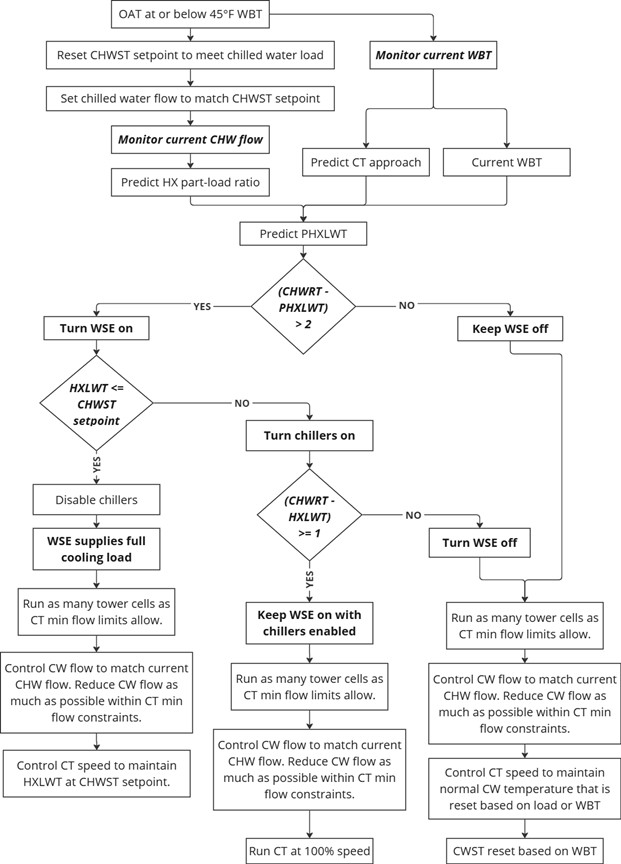
When outdoor dry bulb (OAT) and wet bulb temperatures (WBT) are low enough to enable waterside economizers (WSE), the optimum control sequence of the SOO is described below. Site-specific conditions may require varying this control strategy.
The chilled water supply temperature (CHWST) setpoint is modulated as limits allow while meeting the cooling demand. The chilled water (CHW) flow rate is adjusted to match the desired CHWST setpoint. With known parameters, such as the current CHW flow rate, WBT, and the design conditions of the heat exchanger (HX) and the cooling tower (CT), the CHW temperature leaving the HX can be predicted (PHXLWT).
According to Taylor (2014), the waterside economizer should be disabled when it cannot reduce the chilled water return temperature (CHWRT) (returning from the building) by at least 1°F. Chillers are disabled when the economizer can supply the entire cooling load; conversely, if the cooling demand is not met by the current chilled water supply, chillers are turned on.
As many tower cells as possible should be enabled while making sure the tower flow is within the minimum limits. Condenser water should be maintained at a minimum flow rate that can match the CHW flow at the desired supply temperature setpoint. Meanwhile, the reduced condenser water flow must be compatible with the tower limits through controlling pump speed, staging pumps, and modulating the HX valves.
The condenser water supply temperature (CWST) (entering the HX) equals the heat exchanger leaving water temperature (HXLWT) (leaving the HX) minus the HX approach temperature. The condenser water return temperature (leaving the HX) depends on the cooling load supplied by the HX. In other words, the cooling tower speed and approach are modulated to provide the desired condenser water temperature that can cool the chilled water entering the HX to meet the cooling demand at current wet bulb temperature.
Evaluation of Energy Consumption
Waterside economizers alter the electrical energy consumption of all the motorized components in a central cooling plant. Due to the highly interactive effects between the indoor loads, the CHW loop, condenser water loop, chiller, indoor loads, and outdoor conditions, the energy calculations for a waterside economizer must be done on an hourly basis.
The energy consumption of a water-cooled chilled water plant is the sum of the electrical energy associated with all the systems associated with the plant. Key values that need to be quantified to estimate annual energy consumption are shown in Table 1.
| System Quantification | Values to be Quantified | Energy Consuming Component |
|---|---|---|
| Chilled water loop electricity usage (kWh) |
|
Pump motor |
| Water-cooled chiller compressor electricity usage (kWh) |
|
Compressor motor |
| Cooling load on building / Heat rejected to the outdoors (Btu/h) | Average hourly thermal load on chiller evaporator (Btu/h) | Evaporator |
| Water-cooled chiller condenser heat transfer (Btu/h) | Average hourly Btu/h rejected to the condenser water loop | Condenser |
| Condenser water loop fan electricity usage (kWh) |
|
Cooling tower fan motor |
| Condenser water loop pump electricity usage (kWh) |
|
Pump motor |
| Waterside economizer heat transfer (Btu/h) |
|
|
| Waterside economizer pump electricity usage (kWh) (if present) |
|
Pump motor (if present) |
Components to Measure and Measurement Strategy
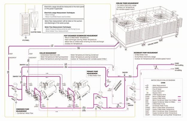
Refer to the chilled water loop, water-cooled chiller, condenser water loop, and waterside economizer system descriptions for specific components to measure.
The measurement boundary and locations for a waterside economizer SOO is highlighted in Figure 3.
Interaction of Waterside Economize with other SOOs
A waterside economizer has potential interactivity with the entire water-cooled chilled water plant. One key assumption when analyzing a waterside economizer is that the cooling loads and operating hours are not changing between the pre- and post-retrofit periods.
Condenser Water Supply Temperature Reset – CWST reset leads to an increase in the amount of time the cooling tower can lower return condenser water temperatures below the CWST setpoint. Waterside economizers inherently incorporate CWST reset. Hence, when evaluating the energy savings from waterside economizing, it is important to document whether an SOO for CWST reset was present pre-retrofit.
Waterside Economizer SOO Calculation Methodology
The annual energy consumption of a water-cooled chilled water plant with a waterside economizer is the sum of the energy for each component system for each hour of the year. The model used must consider the hourly cooling loads and facility operations, outdoor conditions, operating parameters of the systems in the plant, and operations of associated AHU plants. Due to the highly interactive nature of the water-cooled chilled water plant, a detailed plant model or whole facility energy model is needed to estimate annual consumption, based on the actual operational parameters and measured energy consumption of the various systems and components.
Further Reading
-
New York City Department of Buildings. (2020). New York City Energy Conservation Code (NYCECC). Retrieved 2021, from Section C403.5: https://up.codes/viewer/new_york_city/nyc-energy-conservation-code-2020/chapter/C4/commercial-energy-efficiency#C403.5
-
Taylor, S. (2014). How to design & control waterside economizers. ASHRAE Journal, 56, 30-36.