General Overview
The steam condensate recovery system collects condensate from the steam distribution system through steam traps and returns it to the boiler. This makes the system more efficient my reusing heated water that would otherwise be rejected to the environment or sewage system. Before returning to the boiler, the condensate typically passes through a deaerator to remove unwanted oxygen. Condensate can be used to pre-heat make-up water before it enters the boiler, as well as being fed directly back into the boiler. Since condensate is purified water its reuse helps reduce water treatment costs for make-up water.
Components
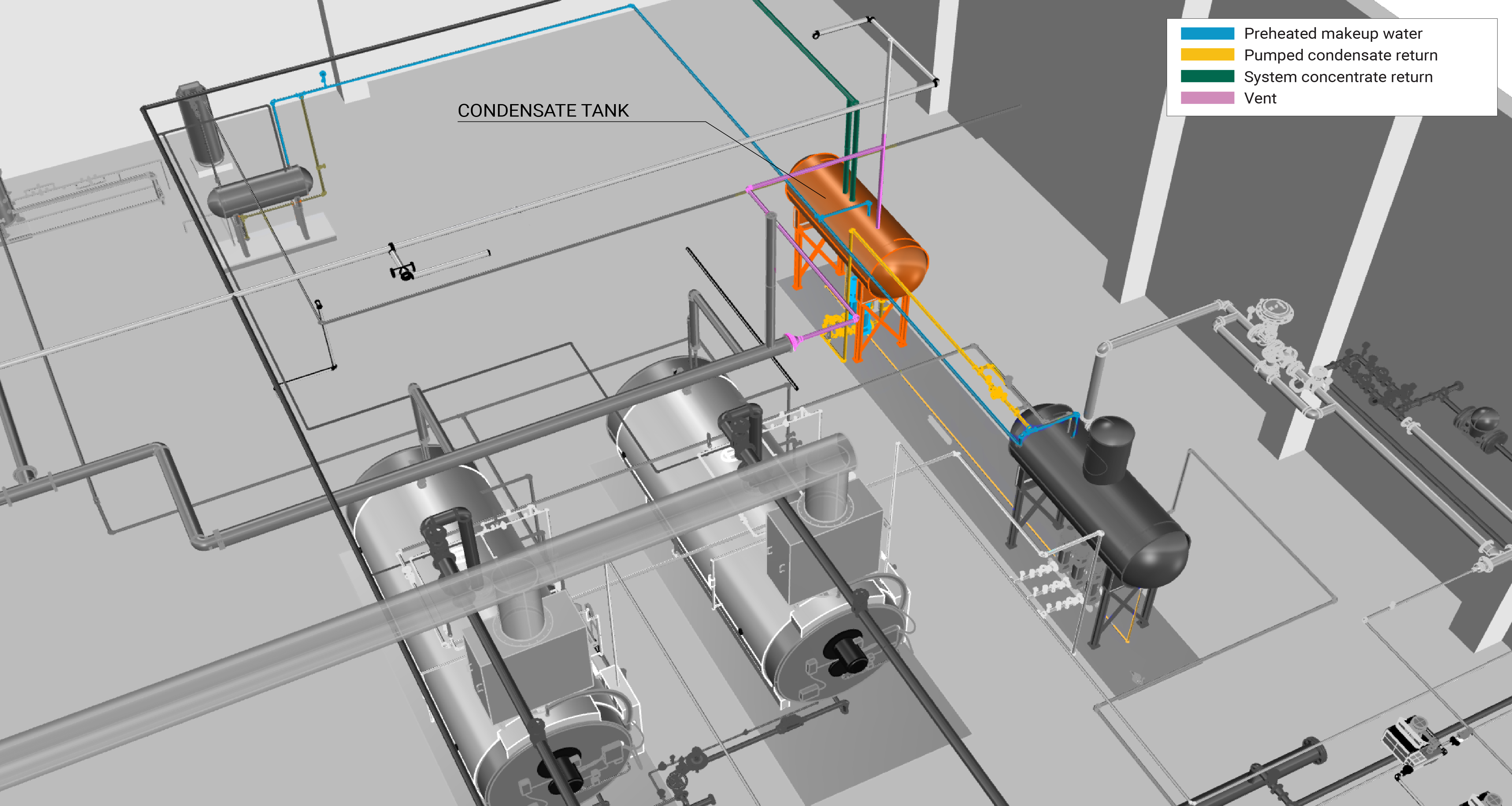
Condensate recovery systems are typically equipped with pumps, pipe networks, and a heat exchanger. Condensate is passed into a receiver tank. The components of a condensate recovery system are shown in Figure 1.

Condensate Pumps
Condensate pumps are responsible for moving condensate from the receiver tank(s) back to the boiler system. In some cases, the receiver tank, pump, and float controls are packaged together. An appropriately-sized pump is crucial to avoiding condensate buildup, which could create problems with terminal units. Learn More
Pipe Networks
The pipe network of a condensate recovery system transports flash steam and condensate. Designs should consider differential of pressure between different lines. It is usually covered with insulation material to minimize heat losses into the environment.
Evaluation of Energy Consumption
The primary purpose of the condensate recovery system on the steam plant is to minimize heat losses and manage condensate that could otherwise be damaging to the steam plant. Generally, the energy related to the condensate system is not quantified; instead, the energy consumption of the overall low-pressure steam plant is quantified. For more information, see Steam Plant.
| Plant Quantification | Values to be Quantified | Energy Consuming Component |
|---|---|---|
| Steam boiler plant fuel consumption (Btu) | Average hourly fuel consumption (Btu/h) | Boiler |
| Steam plant electricity consumption (kWh) |
|
|
Further Reading
-
ASHRAE (2014). “ASHRAE Guideline 14-2014 – Measurement of Energy, Demand, and Water Savings.” Annex A.
-
ASHRAE (2020). “ASHRAE Handbook: HVAC Systems and Equipment,” Chapter 11. STEAM SYSTEMS. I-P Edition.
-
U.S. Department of Energy. (2014). “A Sourcebook for Industry – Energy,” https://www.energy.gov/sites/prod/files/2014/05/f15/steamsourcebook.pdf


