General Overview
A hot water heating (HWH) loop system circulates hot water produced by a hydronic boiler to terminal units, such as heating coils in air handling units or radiant equipment, before returning it to the boiler. This circulation is managed through a piping network using either primary-only or primary-secondary pumps.
Primary-flow System
A primary-flow HWH loop system consists of pumps that circulate hot water from the designated zone to the boilers. The components are shown in Figure 1. There are usually multiple pumps in the system to allow for staging and redundancy. These pumps often pump water into a single common pipe called a header, which allows them to run in parallel and service multiple chillers; however, some facilities have a single pump dedicated to each chiller. Primary-flow systems can be either constant-primary-flow or variable-primary-flow.
A constant-primary-flow system usually has a staged heating system and constant speed HWH loop pumps.
A variable-primary-flow system has primary HWH loop pumps with variable speed drives that regulate the flow of the system based on the heating load of the building. The heating system may be staged or constant.
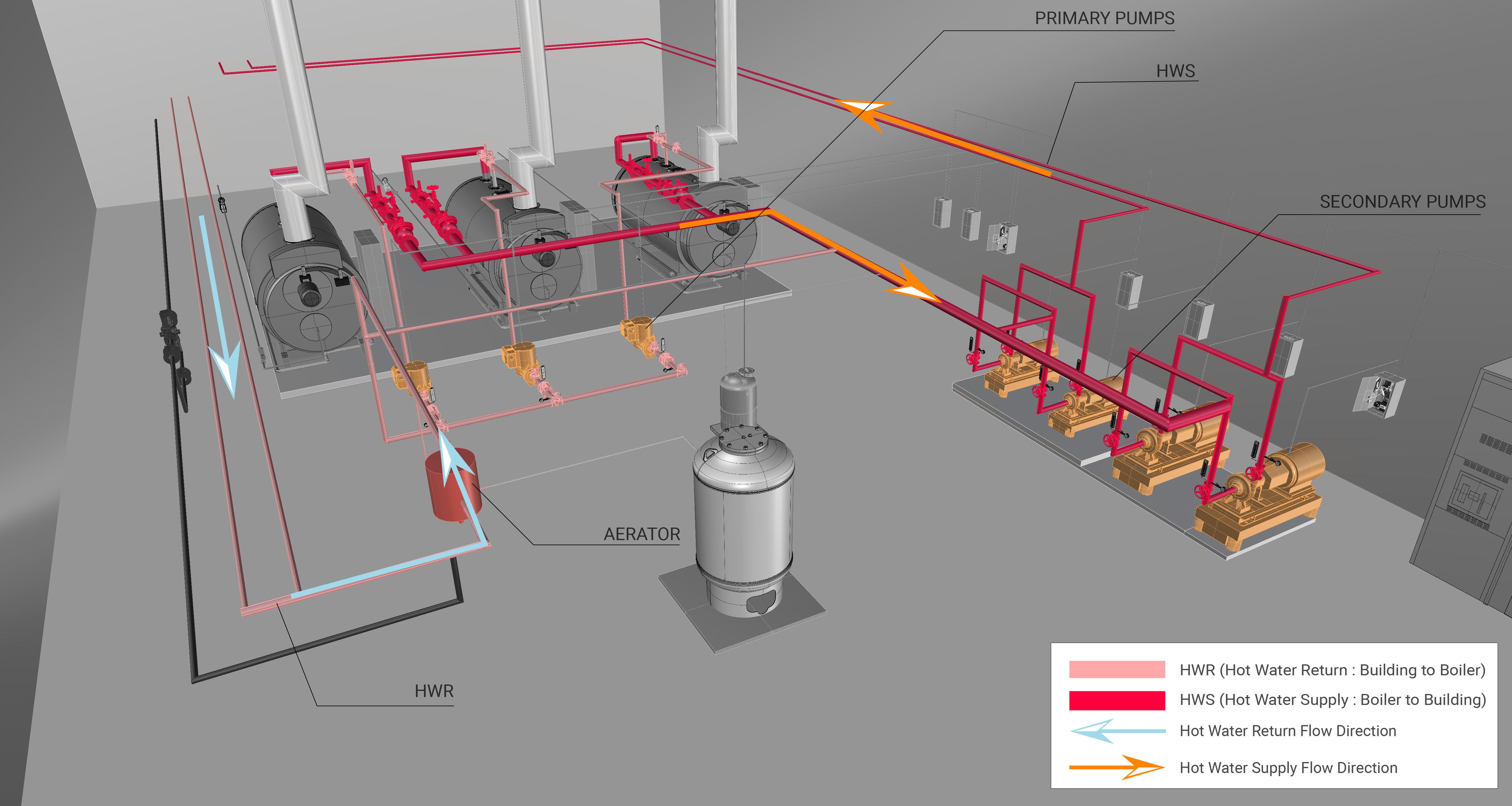
Primary-secondary Flow System
In a system with primary-secondary pumps, the primary pumps circulate the hot water to a low loss header, while the secondary pumps circulate the hot water to the zones in the facility. The components of a primary-secondary flow system are shown in Figure 2. The following arrangements can be found in a primary-secondary flow system:
A constant-primary variable-secondary flow system has constant speed pumps that drive the flow through the primary loop and variable-speed pumps of a separate secondary loop that distribute the heating load to the terminal units. The secondary pumps are controlled by the heat load demand in the terminal units.
A variable-primary variable-secondary flow system has variable-speed pumps on both the primary and secondary loops. They are controlled by the firing rate in the boiler and the heat load demand in the terminal units.
Components
The main components associated with the HWH loop system are primary pumps for primary-flow systems, primary and secondary pumps for primary-secondary flow systems, piping network, and terminal units.
Primary HWH Loop Pump and Motor
A primary HWH loop pump and motor circulate water from the boiler to the building in a primary-only system or to the secondary pump and motor in a primary-secondary system through the piping network. A primary HWH loop pump and motor can operate at constant speed or variable speed based on the design of the hot water plant.
Constant-speed, Constant-volume Pump
A constant-speed, constant-volume pump and motor operates at a single speed to circulate liquid. Learn More
Variable-speed, Variable-volume Pump
A variable-speed, variable-volume pump and motor circulate liquid (e.g., water or water and glycol solution) through a piping network where the flow rate fluctuates as required by the plant and systems they serve. Learn More
Secondary HWH Loop Pump and Motor
A secondary HWH loop pump and motor circulates water from the primary piping network to the building. A secondary HWH loop pump and motor are found in primary-secondary flow systems and can be at constant-speed or can be equipped with variable frequency drives that are controlled by the differential pressure in the secondary piping network.
Constant-speed, Constant-volume Pump
A constant-speed, constant-volume (CSCV) pump and motor operates at a single speed to circulate liquid (e.g., water, water, and glycol solution) through a piping network where the flow rate through the pump does not vary more than 5%. Learn More
Variable-speed, Variable-volume Pump
A variable-speed, variable-volume (VSVV) pump and motor circulate liquid (e.g., water or water and glycol solution) through a piping network where the flow rate fluctuates as required by the plant and systems they serve. Learn More
Primary HWH Loop Piping Network
The primary HWH loop piping network is connected to the boiler and extends through the building to deliver hot water to that facility in a primary-flow system. In a primary-secondary system, the primary piping network is dedicated to circulating water through the boiler. The piping should be covered with insulation that minimizes heat losses with the environment.
Secondary HWH Loop Piping Network
The secondary HWH piping network is connected to the primary piping network to deliver hot water to the facility. The piping should be covered with insulation that minimizes heat losses into the environment.
Terminal Units
Terminal units provide heating to an end-user, where the heat source can be either steam or hot water. Typical terminal units for heating are fan-coil units, unit heaters, radiators, and convectors. The amount of hot water supplied to the terminal units is generally adjusted with a modulating valve controlled by a temperature sensor, which is typically not part of the HWH loop.
Fan-coil Units
A fan-coil unit is a smaller, factory-assembled device that is used to circulate and condition air for either heating or cooling. The coil circulates an energy transfer medium, such as hot water, cold water, steam or a refrigerant. The fan blows air over the coil to heat or cool it. Fan coil units can be connected to ducts, which transport outside air or mixed air, or they can be un-ducted in which case they condition the air in the room.
Unit Heaters
A unit heater is a standalone device containing a fan that blows over a small heat exchanger to provide heat to a space.
Radiators
Radiators are a common terminal unit to distribute heat to space. By routing hot water through the radiator, the heat is transferred to the piping where it relies on radiation as well as free convection to warm a space.
Convectors
Convectors are similar to radiators in how energy is received, but rely almost exclusively on convection to distribute heat to a space. This leads to a cooler temperature to the touch, as well as a smaller terminal unit.
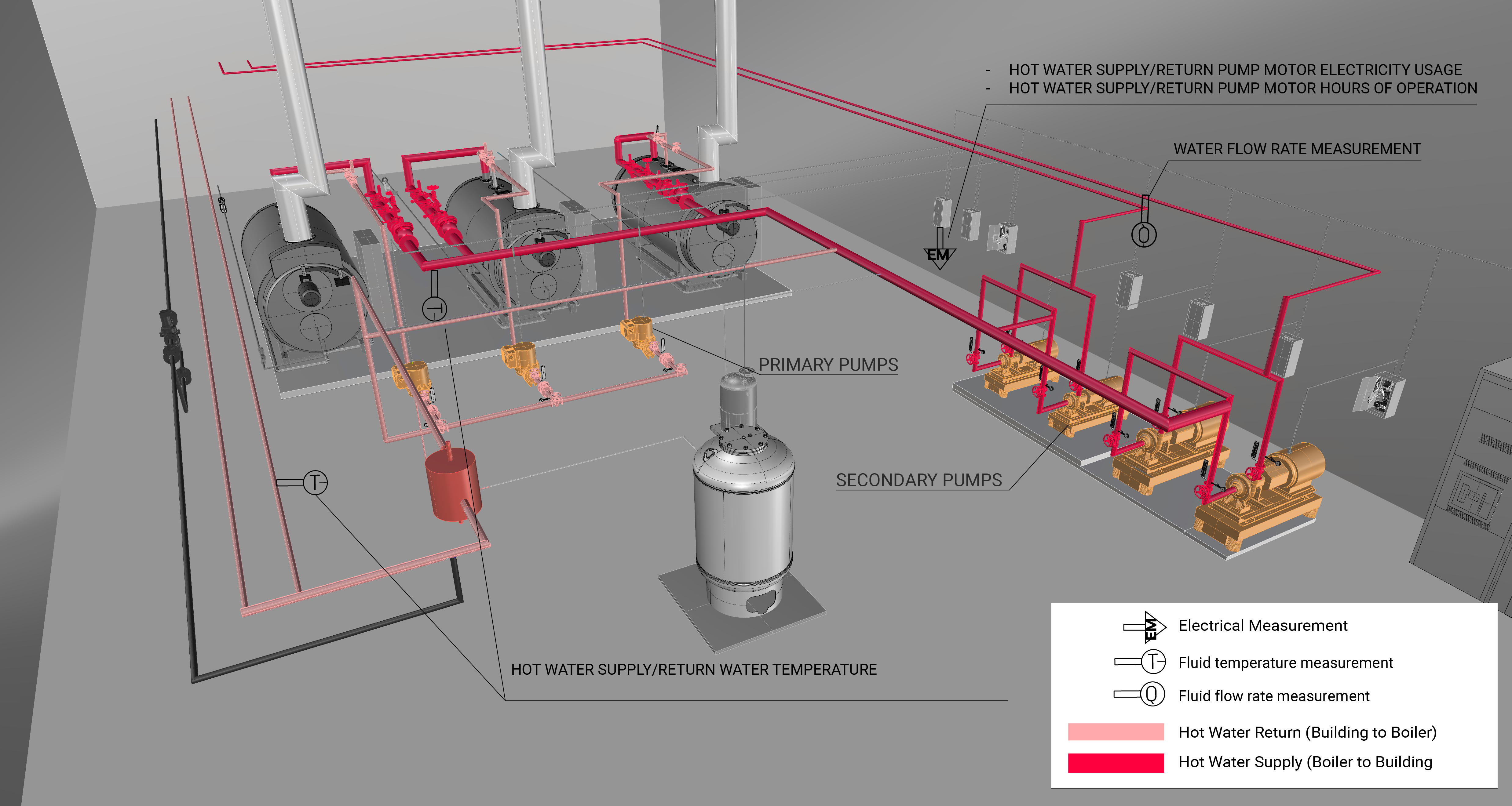
Evaluation of Energy Consumption
The primary energy consumption in a HWH loop is the electricity used to run the pump motors. The heat loss across the piping network contributes to the overall energy consumption for the entire HWH plant–in particular, the boiler system. Table 1 provides a summary of system component measurements and values needed to quantify the annual energy consumption and operating characteristics of a HWH loop system.
| System Quantification | Values to be Quantified | Component to be Measured | Measurements |
|---|---|---|---|
| Primary HWH loop pump electricity usage (kWh) - constant-speed system |
|
Constant-speed pump motor | |
| Primary HWH loop pump electricity usage (kWh) - variable-speed system |
|
Variable-speed pump motor | |
| Secondary HWH loop pump electricity usage (kWh) - variable-speed system (if present) |
|
Variable-speed pump motor | |
| Primary HWH loop water flow – constant speed system | Average hourly water flow (GPM) through a pump | Hourly measurement of water flow rate | |
| Terminal units – heating load delivered | Average hourly Btu rejected from the hot water loop |
Measurement Locations
The measurement locations for a primary-flow and primary-secondary flow hot water loop system are shown in Figure 3.
Further Reading
-
ASHRAE (2020). “ASHRAE Handbook: HVAC Systems and Equipment,” Chapter 13. Hydronic Heating and Cooling. I-P Edition.
-
ASHRAE (2020). “ASHRAE Handbook: HVAC Systems and Equipment,” Chapter 44. Centrifugal Pumps. I-P Edition.