General Overview
The feedwater system usually receives condensate recovered from the condensate recovery system and make-up water (treated fresh water). It maintains water levels in the boiler, extending its lifespan.
Feedwater systems supply fresh water to hot water or steam boilers to make up for losses from boiler blowdown, steam traps, hot water use, or other losses. The feedwater system receives inputs of make-up water and, in steam systems, condensate from the condensate recovery system.
Components
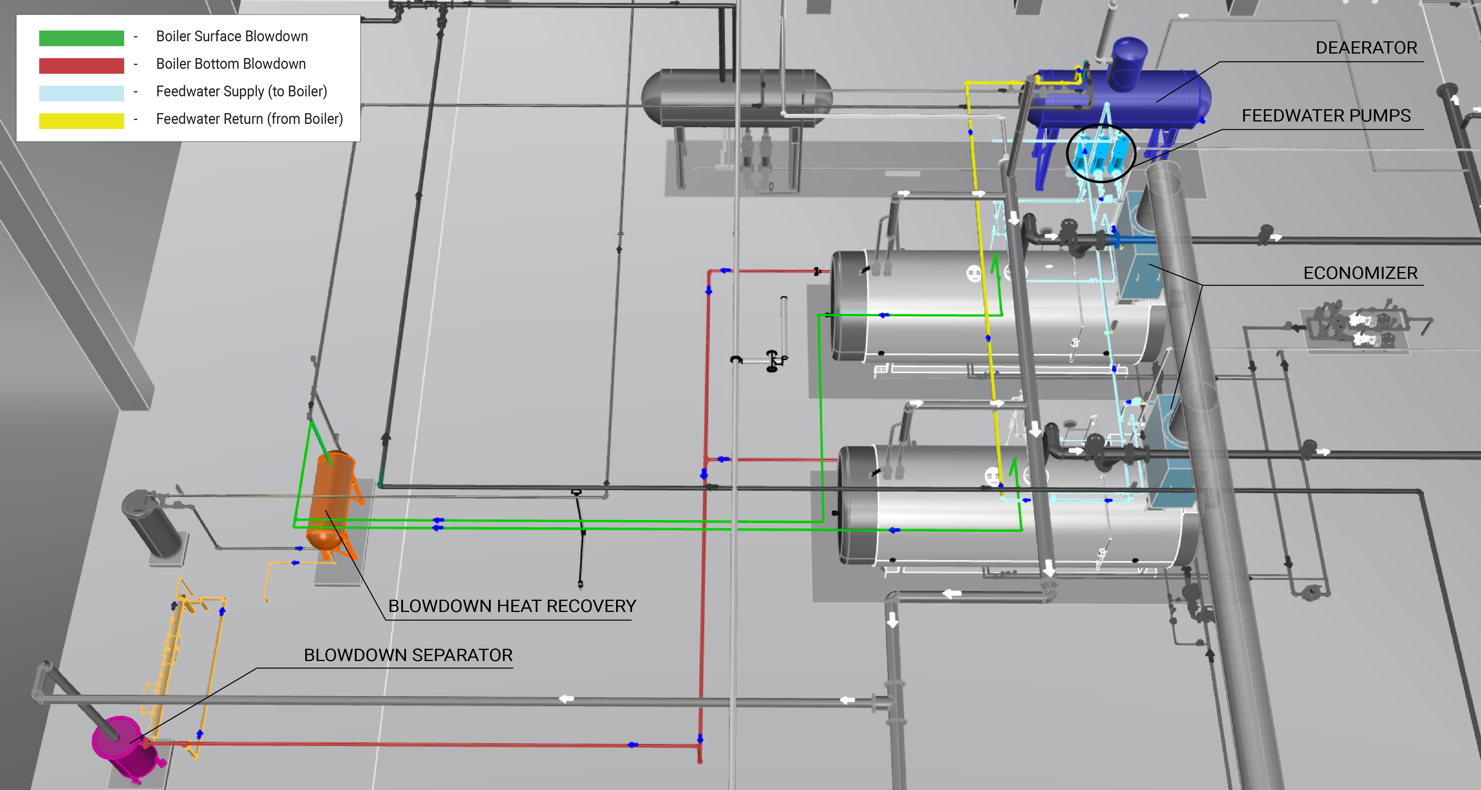
The main components of a boiler feedwater system are one or more feed pumps, and a receiver tank. Feedwater systems may include an economizer, and larger systems also may have a deaerator tank. These components are shown in Figure 1.
Pumps and Motors
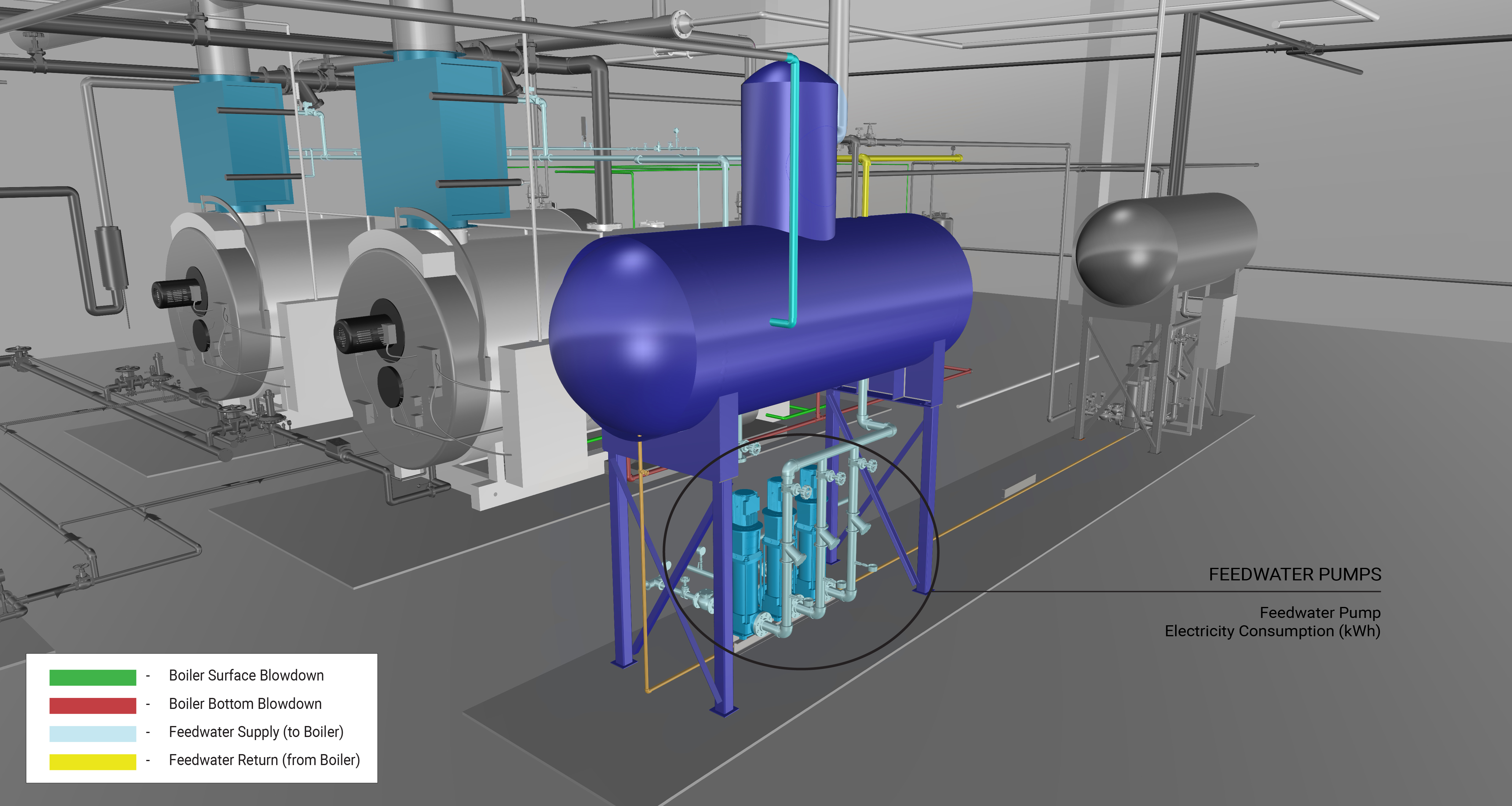
The feedwater pumps and motors inject the feedwater stored in the feedwater tank into the boiler. The pumps and motors are driven by a feedwater controller that monitors the water level of the boiler and the water contaminant levels. When the controller receives the signal, it turns on the pumps and feedwater flows into the boiler.
Constant-speed, Constant-volume Pump
A constant-speed, constant-volume pump and motor operates at a single speed to circulate liquid. Learn More
Variable-speed, Variable-volume Pump
A variable-speed, variable-volume pump and motor circulate liquid (e.g., water or water and glycol solution) through a piping network where the flow rate fluctuates as required by the plant and systems they serve. Learn More
Piping Network
The piping network for a feedwater system can serve one or multiple boilers for a hot water or steam plant where each boiler has its own feedwater valve. The feedwater valve opens and closes based on the boiler controller signal.
Feedwater Tank
The feedwater tank is a chamber that receives make-up water and condensate recovered from the condensate recovery system. The make-up water is treated to remove contaminants and its temperature is increased prior to being discharged into the feedwater tank.
Economizer
An economizer–or flue gas heat recovery unit–is a heat exchanger installed on the stack of a boiler to recover heat from combustion gases discharged through the stack that would otherwise be wasted.
Evaluation of Energy Consumption
The primary energy consumption in a feedwater system is the electricity used to run the pump motors. Table 1 provides a summary of system component measurements and values needed to quantify the annual energy consumption and operating characteristics of the feedwater system.
| System Quantification | Values to be Quantified | Energy Consuming Component | Measurements |
|---|---|---|---|
| Feedwater pump electricity consumption (kWh) |
|
Pump motor |
|
The primary function of the economizer is to reduce fuel consumption by recovering heat from the flue stack to preheat the feedwater before it enters the boiler. This heat recovery improves efficiency and can be reflected in the overall energy consumption of the low-pressure steam plant. For more information see the steam plant.
Measurement Locations
The measurement locations for a feedwater water system are shown in Figure 2.
Further Reading
- ASHRAE (2020). “ASHRAE Handbook: HVAC Systems and Equipment,” Chapter 32. Boilers. I-P Edition.