General Overview
A constant-speed, constant-volume (CSCV) air handling unit provides conditioning to mixed air (a combination of outdoor and return air), discharges the conditioned air into zones, returns air from the zones, and exhausts air to the outdoors. The CSCV system has a constant volumetric airflow rate. The discharge air is conditioned by heating or cooling heat exchangers that are supplied from the heating and cooling loop systems (e.g., steam loop, hot water heating loop, chilled water loop, refrigerant coil). For a more detailed description of the system, refer to the ASHRAE HVAC Systems and Equipment Handbook (2020), Section 4.
Components
The major components of a CSCV system include fans and motors, heat exchanger coils, and dampers. Figure 1 illustrates the components of the CSCV system. In general, mixed air is conditioned by heating or cooling coils that receive energy from the heating or cooling loops, with mechanical valves regulating the energy introduced to the coils. Supply and return fans circulate air to and from the served zones, while dampers control airflow.
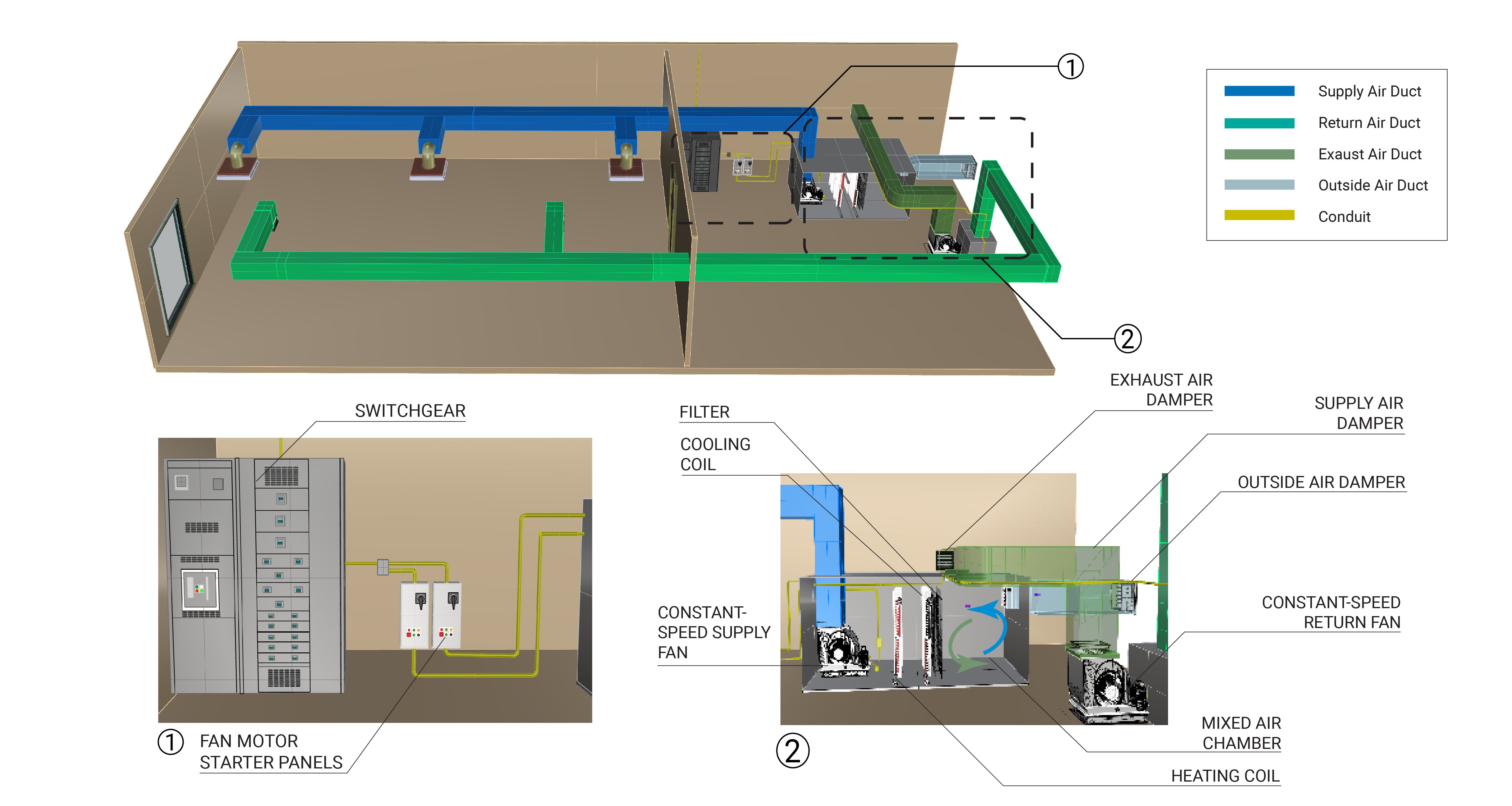
Fan and Motor
The fan motors provide pressure in the system to move air through the duct work. Typically, fans are placed on the return and supply side of the unit to maintain proper airflow. The air is either blown or pulled through filters and heat exchanger coils, depending on the configuration. In a CSCV system, the motors operate in an on/off manner. Learn More
Heat Exchanger (Heating/Cooling Coils)
The heat exchanger includes a set of heating and cooling coils that provide heating or cooling to the air before it is discharged from the AHU. Mechanical valves regulate the amount of energy introduced from the loop to the heat exchangers, which control the energy supplied to the discharge air. Learn More
Dampers
Dampers are generally interlocked and are controlled to supply appropriate quantities of fresh air to the AHU and exhaust air to the outdoors. The dampers can also be set to maintain desired building pressures.
Evaluation of Energy Consumption
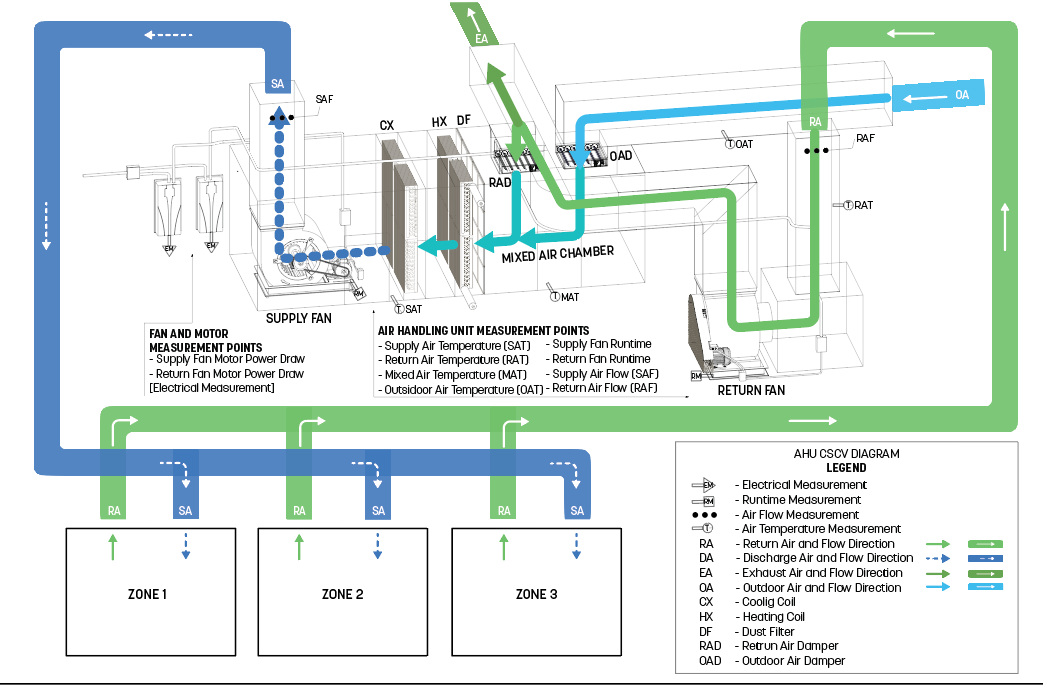
The primary energy consumption of a CSCV is the electricity that is used to run the fan and motor and the energy transferred to the air for heating and cooling. Table 1 provides a summary of measurements needed to quantify the annual consumption and operating characteristics of the CSCV pump and motor.
| System Quantification | Values to be Quantified | Energy Consuming Component | Measurements |
|---|---|---|---|
| Air handling unit electricity usage (kWh) | Average hourly supply and return fan motor (kWh) | Fan motors | Spot measurements of true RMS power |
| Heating/cooling load on building (Btu/h) |
|
Heating/cooling coils |
|
Measurement Locations
The measurement locations for a CSCV AHU are shown in Figure 2.
Further Reading
-
ASHRAE (2014). “ASHRAE Guideline 14-2014 – Measurement of Energy, Demand, and Water Savings.” Annex A.
-
ASHRAE (2020). “ASHRAE Handbook: HVAC Systems and Equipment,” Chapter 1. HVAC SYSTEM ANALYSIS AND SELECTION. I-P Edition.
-
ASHRAE (2020). “ASHRAE Handbook: HVAC Systems and Equipment,” Chapter 4. AIR HANDLING AND DISTRIBUTION. I-P Edition.