General Overview
The air handling plant (AHP) uses input energy (e.g., electricity, heated water, or chilled water) to condition the air and maintain required indoor environmental conditions such as temperature, humidity, and fresh air supply. The AHP may consist of various types of air handling units (AHUs) at the system level, including rooftop units, fan coil units, and constant-speed units, which will be discussed in the system-level descriptions. For a more detailed overview of various system configurations for this plant, please refer to the ASHRAE HVAC Systems and Equipment Handbook (2020), Section 4 – Air Handling and Distribution.
Systems
The systems and components that make up the air handling plant are listed and described further in Table 1 below. It should be noted that for a given AHP, there may be a mix of air handling systems installed (e.g., constant-speed, constant-volume, variable air volume) and configurations (e.g., split heat pump, rooftop unit).
Constant-speed, Constant-volume (CSCV) AHU
A CSCV air handling system provides heating, cooling, and ventilation air to a space in a facility. The AHU is built out of various sections on-site. The volume of outside air in the AHU can be modulated from 0% (outside air damper fully closed) to a typical ventilation rate (minimum outside air damper position) and in some cases can provide 100% outside air (economizer mode). Learn More
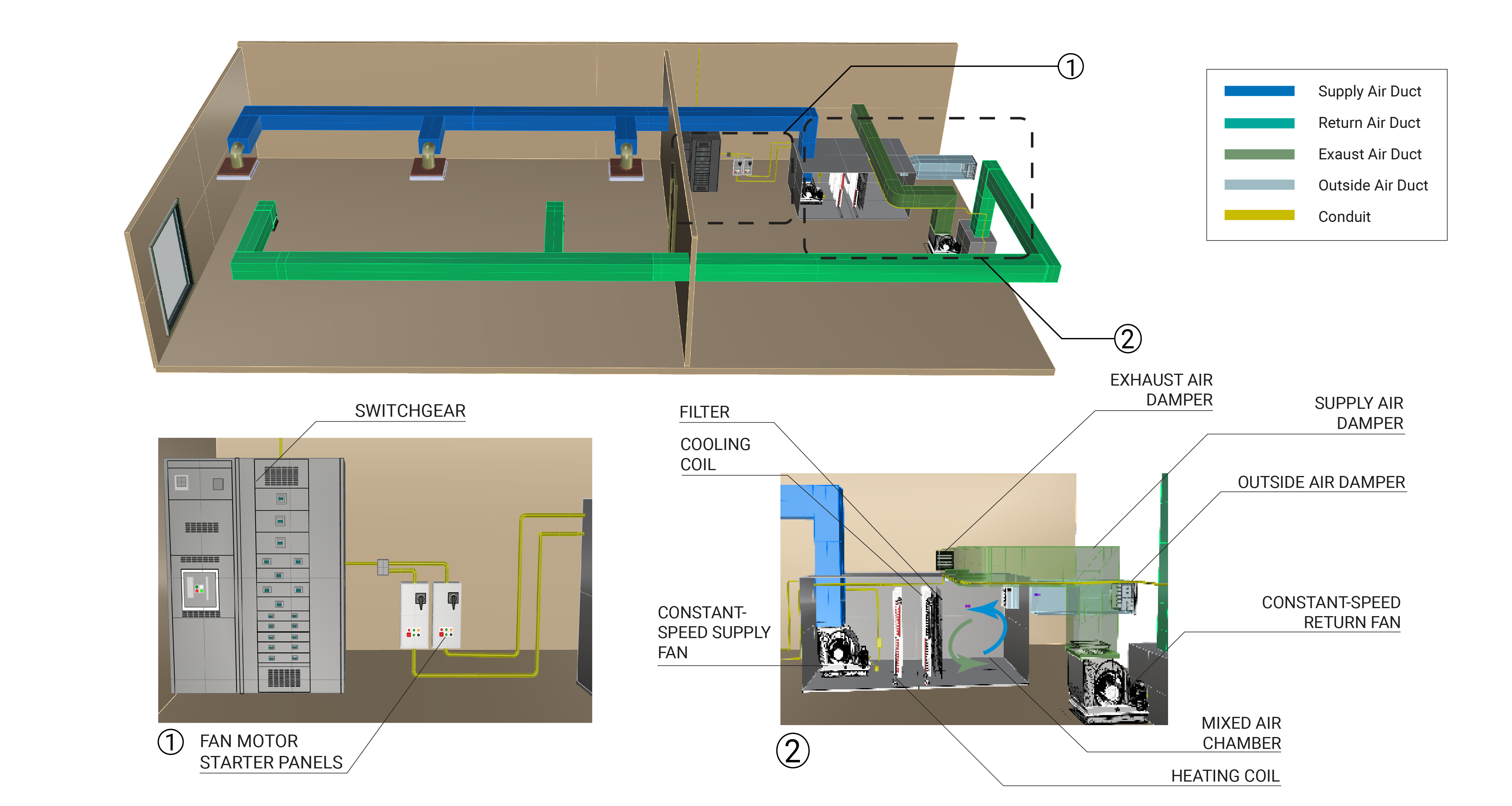
Dual-speed, Constant-Volume (DSCV) AHU
A DSCV system is similar to a CSCV system, except the fan motors in the AHU have a high and low speed setting. This configuration allows the AHU to operate at a slower speed during setbacks at unoccupied times, such as night or weekends.
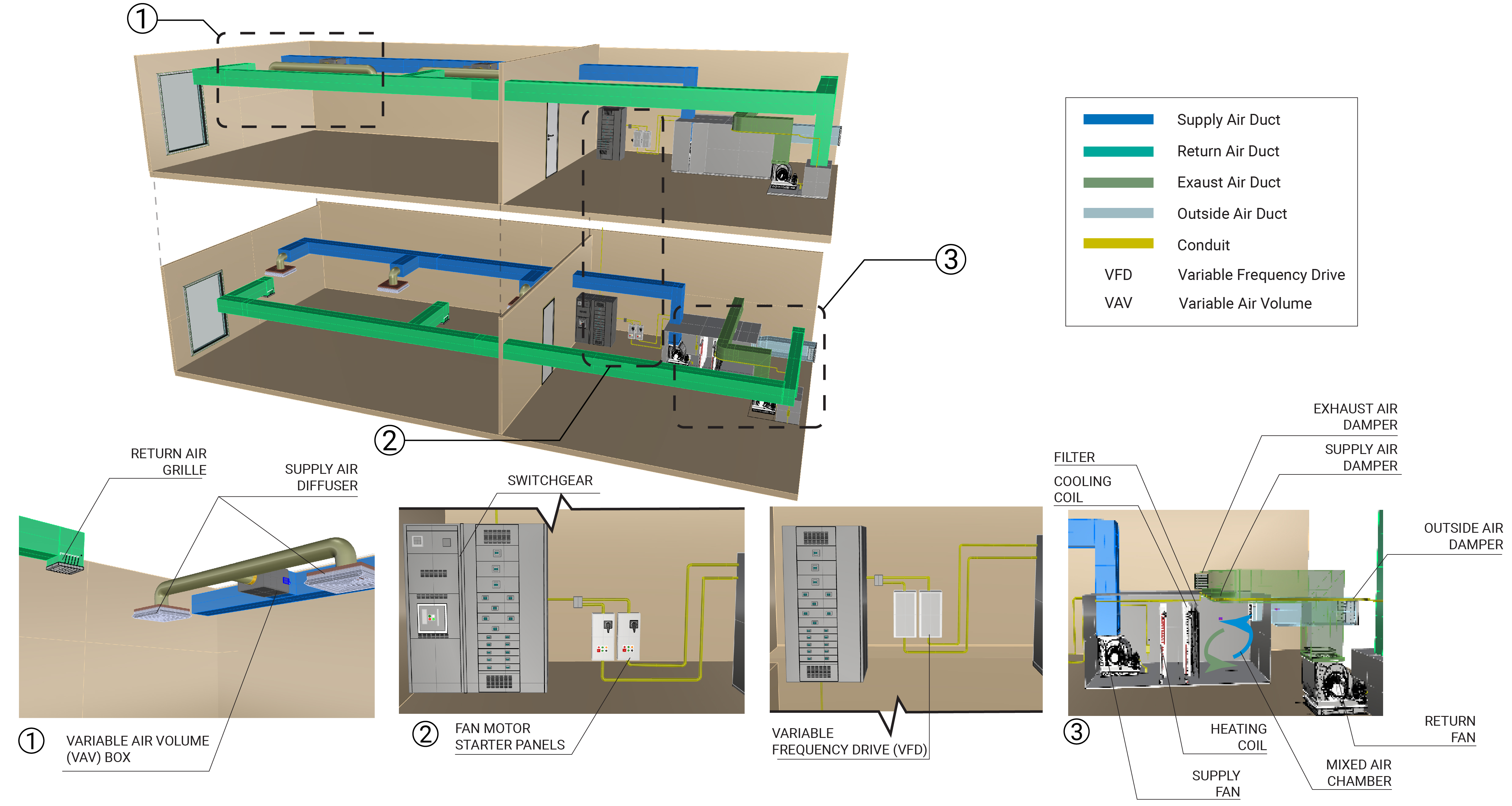
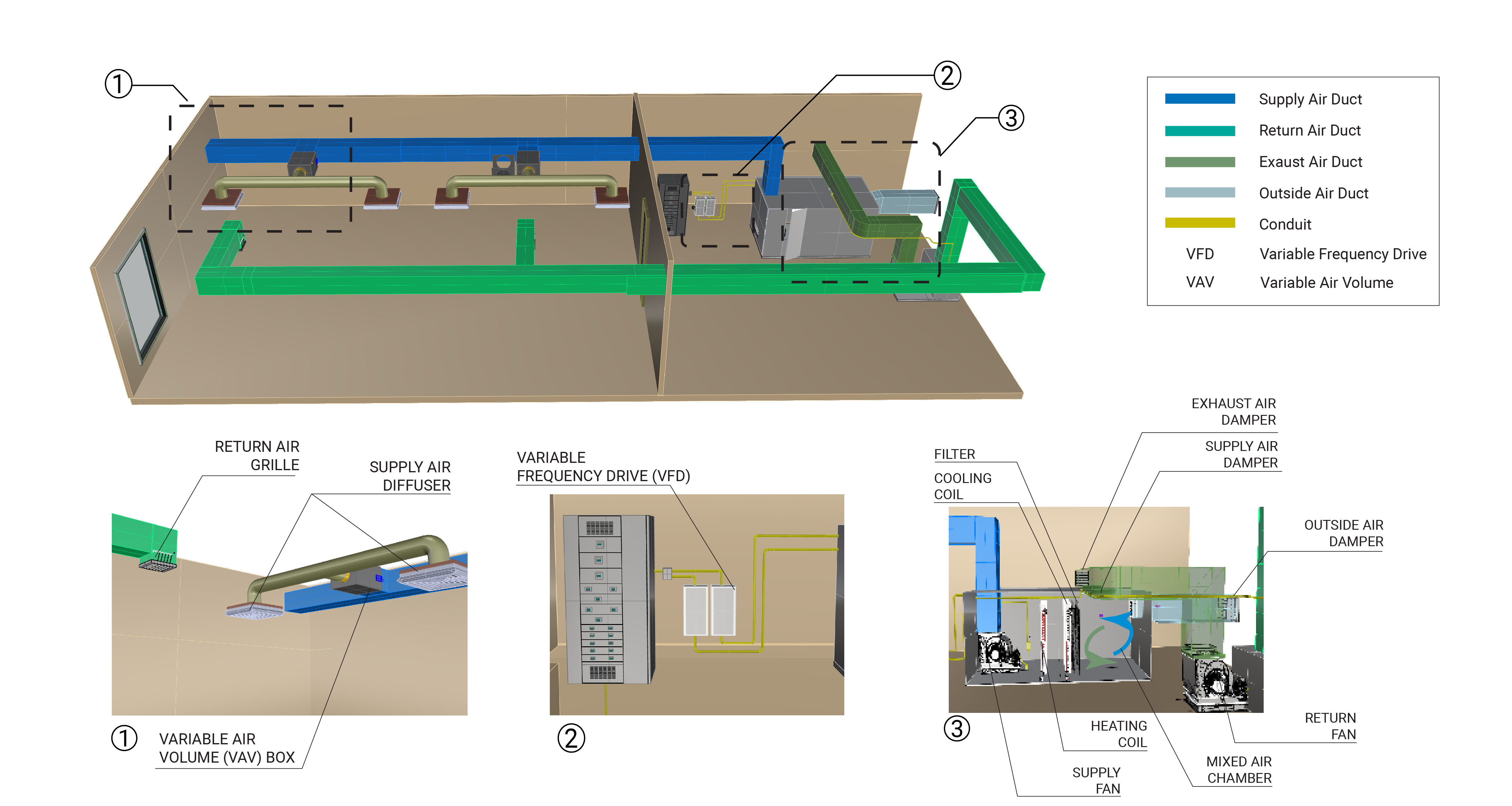
Variable-air Volume (VAV) AHU
A VAV system consists of a main AHU and multiple VAV boxes that serve different zones. The AHU has fan motors that are equipped with variable frequency drives (VFDs) that allow the fan speed (and associated air volume) to modulate as the building demand changes. VAV boxes have dampers that can regulate the flow of air and ventilation into a zone. AHUs modulate airflow in response to changes in the VAV box damper position. VAV boxes are installed in the supply air ductwork in the zones served and are generally installed with a heating coil, also known as a reheat coil. This enables the system to adjust the supply air temperature to prevent over-cooling a space. The VAV system allows for space temperature and ventilation air control in each zone. VAV boxes are usually set with a minimum damper position associated with the minimum required ventilation airflow needed for the zone.
Learn More
Air-to-air Energy Recovery
Air-to-air heat exchangers transfer energy between two airstreams that must be at different temperatures for sensible heat transfer and different moisture contents for latent heat transfer. Learn More
Dedicated Outdoor Air System (DOAS)
A DOAS system is designed to heat, cool, humidify, dehumidify, and filter ventilation air independent of the space heating and cooling needs of a facility. A DOAS can generally provide limited space heating and cooling, but only as a byproduct of the required volumes of ventilation air provided to a space or zone.
Fan Coil Unit (FCU)
An FCU is a smaller, factory-assembled device that circulates and conditions air.
Split Heat Pump (HP)
An HP is a split system that provides heating or cooling and is comprised of an indoor unit with a fan and evaporator coil and an outdoor unit with a fan and condenser coil.
Fuel-Fired Furnace
A fuel-burning device that heats air for space conditioning.
Rooftop Unit (RTU)
A roof-mounted packaged system that provides heating, cooling, and ventilation while supplying air directly to a space below or into a set of ducts.
Induction Unit (non-fan powered)
A system that uses a fast-moving primary air stream (usually created by a set of nozzles) to induce air from the space to be drawn through the unit and mixed with the primary air stream. The primary air stream is generated by a separate system such as a CSCV AHU or a DOAS.
Evaluation of Energy Consumption
The energy consumption of an air handling plant (AHP) is the total energy used by each air handling unit (AHU) system, including electricity for the supply and return fans and the energy required to heat or cool the air. Heating and cooling energy may come from a central heating or cooling plant or be generated directly at the AHU, such as natural gas for heating or electricity for compressor-based cooling. Table 1 summarizes the system component measurements and values needed to quantify the annual energy consumption of an AHP.
| System(s) | Values to Quantify | Energy Consuming Component |
|---|---|---|
|
|
|
| Heat pump | Average hourly heat pump kWh (includes supply and condenser fan motors and compressor motors) |
|
| Fuel fired furnace |
|
|
| Rooftop Unit | Average hourly fuel consumption: average hourly rooftop unit kWh (includes supply and condenser fan motors and compressor motors) |
|
| Induction Unit |
Average Btu/h at coils |
Heating coil |
Further Reading
-
ASHRAE (2020). “ASHRAE Handbook: HVAC Systems and Equipment,” Chapter 1. HVAC SYSTEM ANALYSIS AND SELECTION. I-P Edition.
-
ASHRAE (2020). “ASHRAE Handbook: HVAC Systems and Equipment,” Chapter 4. AIR HANDLING AND DISTRIBUTION. I-P Edition.
-
ASHRAE (2019). “ANSI/ASHRAE/IES Standard 90.1-2019 – Energy Standard for Buildings Except Low-Rise Residential Buildings”. ASHRAE.
-
Taylor, S (2014). “Return Fans in VAV Systems”. ASHRAE Journal, Vol. 56; pp. 54-58.