General Overview
A variable-speed, variable-volume (VSVV) air handling system provides conditioning to mixed air (a combination of outdoor and return air), discharges the conditioned air into zones, returns air from the zones, and exhausts air to the outdoors. The served zones are typically equipped with variable-air volume boxes (VAV), which allow for zone-specific control of supply airflow. The overall airflow of the air handling unit (AHU) is modulated using variable-frequency drives (VFDs) on the supply and return fan motors, typically based on the static pressure in the duct system (i.e., static pressure reset). For a more detailed description of the system, refer to the ASHRAE HVAC Systems and Equipment Handbook (2020), Section 4.
Components
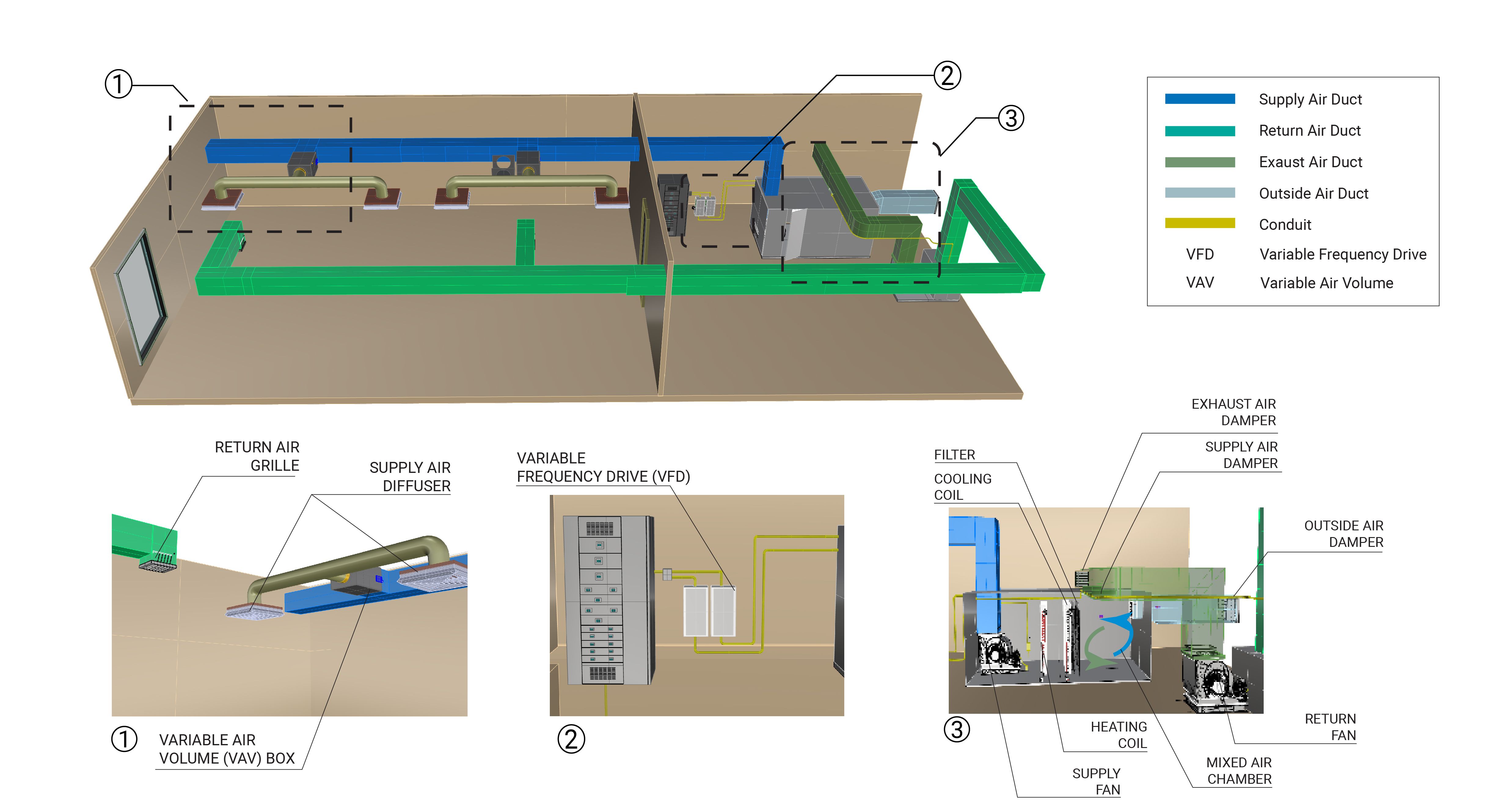
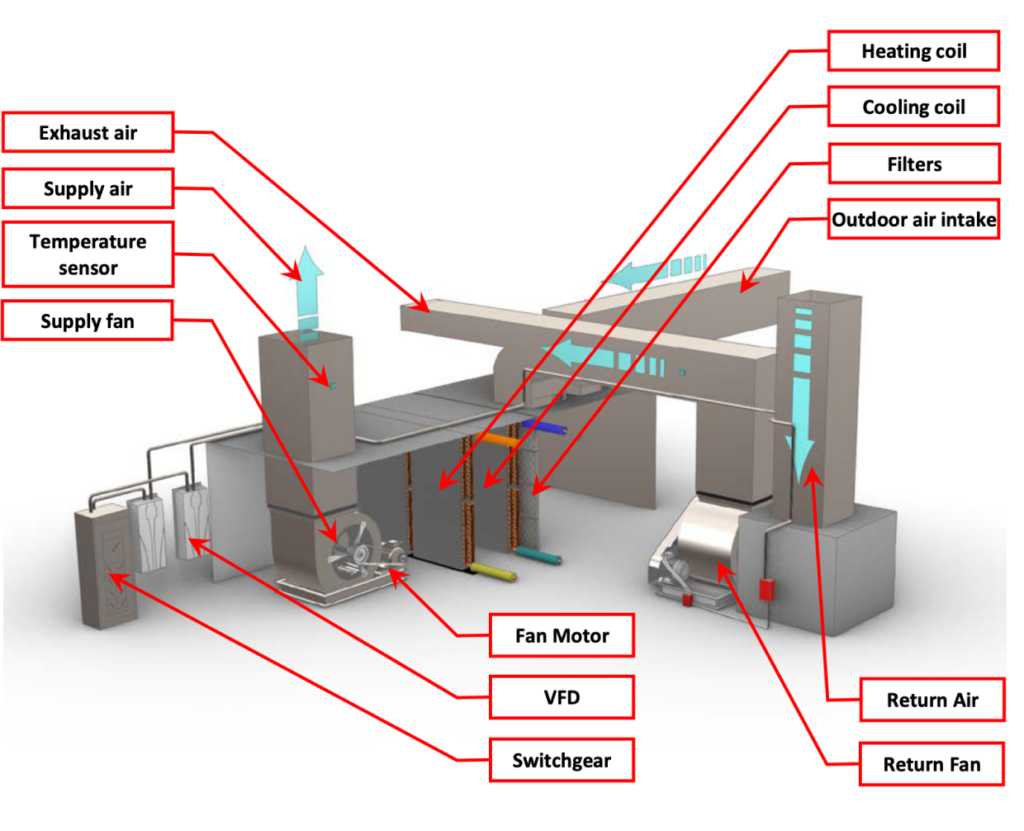
The major components of a VSVV system are the fans and motors, motor VFDs, heat exchanger coils, dampers, and VAV boxes. The components associated with the VSVV are shown in Figure 1. In general, the mixed air is conditioned by heating or cooling coils that use the output of the heating or cooling loops, using mechanical valves to regulate the amount of energy introduced to the coils. Supply and return fans with VFDs and dampers control airflows inside the main AHU. Dampers in the VAV boxes control zone airflows. Occasionally, a VAV box is equipped with a supply fan.
AHU Fan Motors and Variable-frequency Drives
The fan motors with VFDs provide pressure in the system to move air through the duct work. Typically, fans are placed on the return and supply side of the unit to maintain proper airflow. The air is blown through filters and heat exchanger coils to be conditioned. Fan speeds are varied based on the need for conditioned or ventilation air in the zones served. Learn More
Heat Exchanger (Heating/Cooling Coils)
The heat exchanger includes a set of heating and cooling coils, which provide heating or cooling to the air before it is discharged from the AHU. Mechanical valves regulate the amount of heating or cooling water (or steam) introduced from the loop to the heat exchangers that control the energy supplied to the discharge air. Learn More
Dampers
Dampers are controlled to supply appropriate quantities of fresh air to the AHU and exhaust air to the outdoors. The dampers can also be set to maintain desired building pressures.
Variable-air Volume (VAV) Box
A device that includes a damper to control zone specific airflow, a VAV box is sometimes equipped with a fan based on the overall system design. Dampers in the VAV boxes control zone airflows based on the space thermostat setpoint. VAV boxes are typically equipped with reheat coils to prevent over-cooling of zones with low cooling loads and high ventilation air requirements.
Evaluation of Energy Consumption
The energy consumption of a VSVV air handling system is electricity for the fan motors and VFD, thermal energy for heating or cooling across the VSVV AHU heat exchanger, and the electricity or thermal energy used at the VAV reheat boxes. Table 1 provides a summary of the components and operating characteristics of a variable speed system.
| System Quantification | Values to be Quantified | Energy Consuming Component | Measurements |
|---|---|---|---|
| Air handling unit electricity usage (kWh) | Hourly fan motor kWh | Fan motors and associated VFDs |
|
| AHU heating/cooling load on building |
|
Heating/cooling coils | Water flow rate and temperature difference across the loop feeding the VAV box reheat coils |
| VAV box consumption (if applicable) | Hourly reheat kWh | Electric reheat coil (if present) | Hourly true RMS energy |
| VAV box consumption (if applicable) | Hourly thermal load reheat coils (Btuh) | Hot water or steam reheat coil | Airflow rate and temperature difference across the heating/cooling coil |
| VAV box consumption (if applicable) | Hourly fan motor kWh | Fan motor (if present) | Hourly true RMS energy |
Measurement Locations
The measurement locations for a VSVV air handling system are schematically shown in Figure 2.
Further Reading
-
ASHRAE (2014). “ASHRAE Guideline 14-2014 – Measurement of Energy, Demand, and Water Savings.” Annex A.
-
ASHRAE (2020). “ASHRAE Handbook: HVAC Systems and Equipment,” Chapter 1. HVAC SYSTEM ANALYSIS AND SELECTION. I-P Edition.
-
ASHRAE (2020). “ASHRAE Handbook: HVAC Systems and Equipment,” Chapter 4. AIR HANDLING AND DISTRIBUTION. I-P Edition.
-
Li, Y. (2015). “Variable Frequency Drive Applications in HVAC Systems”, in M. Chomat (ed.), New Applications of Electric Drives, IntechOpen, London. 10.5772/61782.