General Overview
An air-to-air energy recovery (AAER) system consists of a heat exchanger component, air ducts, and any associated device for its operation. AAER systems extract sensible (and sometimes latent) energy from a previously conditioned “outgoing” airstream and use that energy to pre-condition a separate “incoming” air stream. Typically, the outgoing airstream is drawn from occupied spaces in a building, and the incoming air is from the outdoors. The two airstreams must be at different temperatures for sensible heat transfer and different moisture contents for latent transfer. For a more detailed description of the system, refer to the ASHRAE HVAC Systems and Equipment Handbook (2020), Chapter 26.
Components
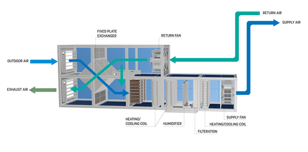
Figure 1 shows the main components associated with a fixed plate heat exchanger including the heat exchanger, air ducts and fan and motors. In a AAER with a rotary wheel heat exchanger there is also a motor used to power the rotary wheel.
Heat Exchangers
The heat exchanger transfers energy between the two airstreams. The most common air-to-air heat exchangers as defined by ASHRAE are listed below. The energy transfer effectiveness in a heat exchanger relies on its configuration, the material properties of the energy exchange surface, and a design that maximizes the contact of the airstream with the heat exchange surface.
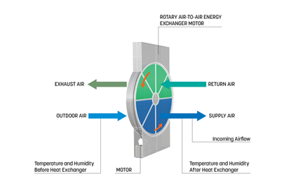
Rotary Air-to-air Energy Exchanger
A rotary wheel exchanger consists of a belt driven wheel that is built up by a matrix of foils. The wheel rotates and moves through both the incoming and outgoing air streams, effectively transferring heat between them. The pressure drop and efficiency of the exchanger depends on the wheel diameter and density of corrugation. Most rotary wheel exchangers transfer both sensible heat and latent energy. Figure 3 shows an example of a rotary wheel heat exchanger. Learn More
Fixed Plate Heat Exchanger
A fixed plate heat exchanger functions by providing neighboring channels, separated by plates, for airstreams to pass through and transfer energy. The channel separation determines both the pressure drop and efficiency of the heat exchanger. Many fixed plate heat exchangers only transfer sensible heat, but they can be designed to transfer latent energy (i.e., moisture) as well, depending on the material used.
Coil Energy Recovery (Runaround) Loop
Coil energy recovery loops, also known as runaround loops, make use of a heat exchanging coil that connects the incoming and outgoing exhaust air streams. The loop contains a heat transfer fluid (i.e., water, glycol) and a pump to move the liquid between both streams. Coil energy recovery loops transfer sensible heat only.
Heat Pipe Heat Exchanger
Heat pipe heat exchangers operate by using a working fluid that changes phases to transfer heat. As shown in Figure 5, one side of the heat pipe is placed in the exhaust stream and the other is placed in the supply stream, causing one side of the pipe to undergo evaporation and the other side to undergo condensation, effectively transferring heat. Heat pipe heat exchangers transfer sensible heat only.
Air Duct
Ducts transport air to and from served zones, heat recovery units and air handling units. Duct systems often include dampers and turning vanes to control flow volume and reduce pressure losses, which can directly impact system efficiency.
Rotary Air-to-Air Energy Exchanger Motor
Most heat exchangers are passive devices and rely on the fan and motor components in other systems to move air through them. In the case of a rotary air-to-air energy exchanger, the heat exchange medium is rotated through the airstreams, where the exchanger medium picks up or releases heat and possibly moisture. A small constant or variable speed motor is needed to rotate the heat exchanger.
Evaluation of Energy Consumption
The primary effect of air-to-air energy recovery is to reduce fuel and/or electricity consumption by capturing waste heat. A heat exchanger will increase the static pressure in the air streams which requires additional fan motor energy. In a rotary wheel configuration, the motor that drives the wheel should be considered when estimating the energy impact. The impact of the AAER on both temperature and humidity must be considered to gain a full picture of its energy impact.
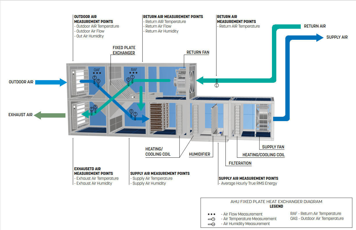
Table 1 provides a summary of the components to measure to arrive at values needed to quantify the annual energy consumption of a heat recovery system.
| System Quantification | Values to be Quantified | Energy Saving Component | Measurements |
|---|---|---|---|
| Heat Recovered |
|
Heat Exchanger |
|
| Heat recovery system electricity consumption (kWh) (if applicable) | Average hourly fan motor (and rotary wheel motor if applicable) kWh | Fan motor (and rotary wheel motor if applicable) | Hourly measurement of true RMS power |
Measurement Locations
The measurement locations for a heat recovery system are shown in Figure 7.
Further Reading
-
ASHRAE (2020). “ASHRAE Handbook: HVAC Systems and Equipment,” Chapter 1. HVAC SYSTEM ANALYSIS AND SELECTION. I-P Edition.
-
ASHRAE (2020). “ASHRAE Handbook: HVAC Systems and Equipment,” Chapter 26. AIR-TO-AIR ENERGY RECOVERY EQUIPMENT. I-P Edition.
-
CenterPoint Energy (2022). “Runaround Loops.” Energy Recovery Systems. https://www.centerpointenergy.com/en-us/Services/Pages/Runaround-loops-MN.aspx?sa=MN&au=bus
-
Heatex (2022). “Heat Exchanger Basics.” https://www.heatex.com/knowledge/heat-exchanger-basics. National Renewable Energy Laboratory (2003). “Laboratories for the 21st Century: Best Practices” https://www.nrel.gov/docs/fy04osti/34349.pdf
-
Paulina Kanaś (2019).” The influence of geometrical parameters on heat and mass transfer processes in rotary heat exchangers.” SN Applied Sciences.