General Overview
A steam distribution system is responsible for distributing the steam produced by a steam boiler system as well as handling any condensate generated in the process. Common configurations for steam distribution systems include one-pipe and two-pipe systems. The main focus here is on two-pipe systems, as they are common in larger facilities. In a two-pipe system, the condensate is handled by a dedicated return line and is kept separate from any steam. The condensate return line can be treated as its own system and is discussed in a separate protocol and procedure document.
Components
Steam Heater and Piping Network
A steam heater acts as a heat reservoir for the distribution loops throughout the building. This reservoir allows for the boilers to run at a constant rate while the heating load of the building fluctuates.
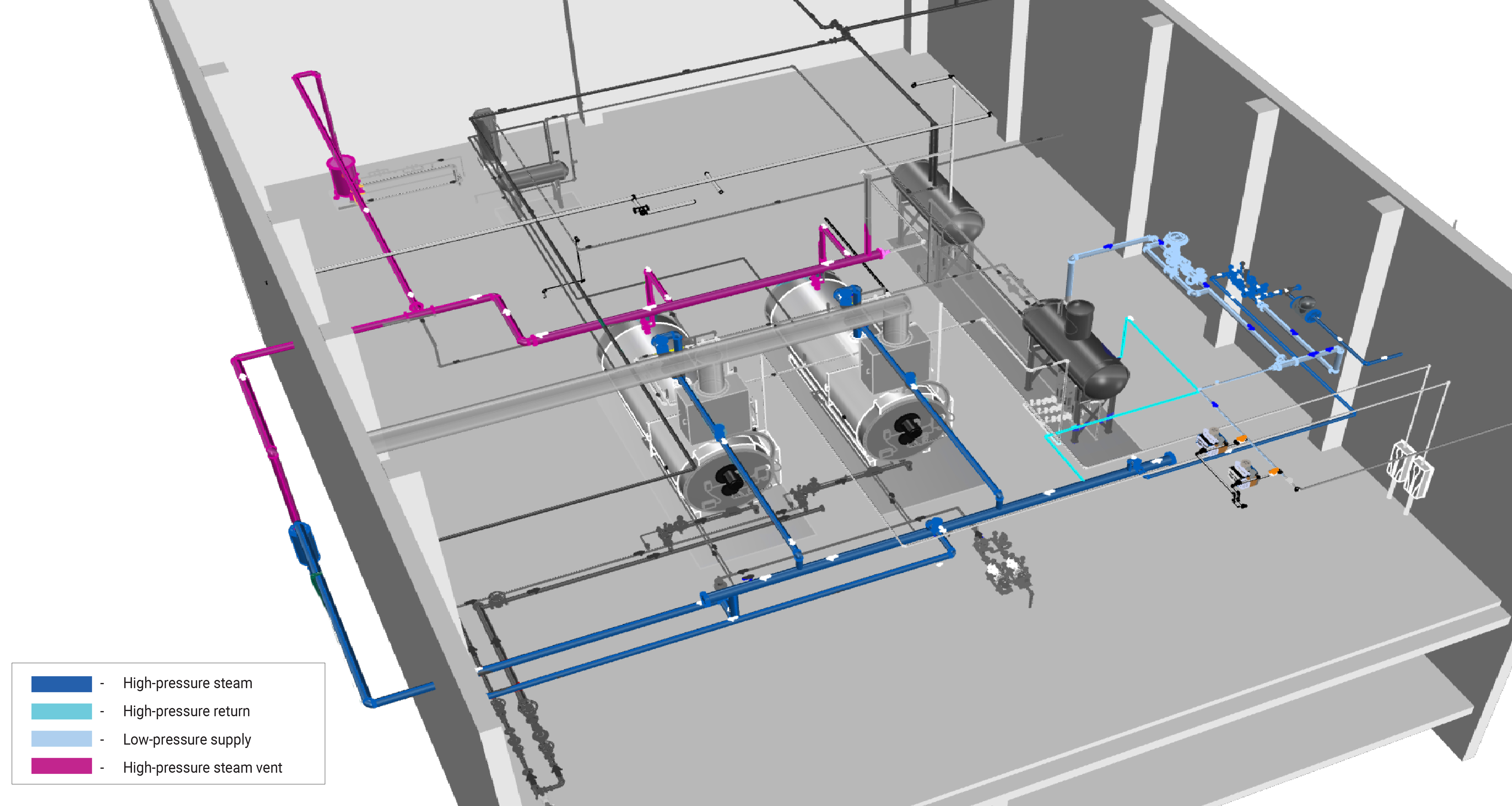
The steam piping network is equipped with valves, fittings, and connections to properly maintain the pressure differential in the system. It is covered with piping insulation that minimizes heat losses within the environment.
Terminal Units
Terminal units provide heating to an end-user, where the heat source can be either steam or hot water. Typical terminal units for heating are fan-coil units, unit heaters, radiators, and convectors. The amount of steam supplied to the terminal units is generally adjusted with a modulating valve controlled by a temperature sensor, which is not typically part of the steam distribution system.
Fan-coil units
A fan-coil unit is a smaller, factory-assembled device that is used to circulate and condition air for either heating or cooling. The coil circulates an energy transfer medium, such as hot water, cold water, steam or a refrigerant. The fan blows air over the coil to heat or cool it. Fan coil units can be connected to ducts, which transport outside air or mixed air, or they can be un-ducted in which case they condition the air in the room.
Unit heaters
A unit heater is a standalone device containing a fan that blows over a small heat exchanger containing steam or some other heating source to provide heat to a space.
Radiators
Radiators are a common terminal unit used to distribute heat to a space. When routing steam through a radiator, the heat transfers to the piping, where it relies on radiation as well as free convection to warm a space.
Convectors
Convectors are similar to radiators in how energy is received, but rely almost exclusively on convection to distribute heat to a space. This leads to a cooler temperature to the touch, as well as a smaller terminal unit.
Heat Exchanger
Steam distribution systems sometimes include steam-to-water heat exchangers that transfer heat to a heating hot water loop or a domestic hot water system. Converters and heated storage tanks can also be classified as steam-to-water heat exchangers.
Steam Traps
Steam traps separate the condensate water from the steam distribution system, ensuring proper distribution and system efficiency. Steam traps can be mechanical or thermostatic.
Mechanical traps rely on the density difference between condensate and steam. Common mechanical traps include the float traps and bucket traps, which both rely on the buoyancy effect.
Thermostatic traps rely on the temperature difference between the condensate and steam. Common thermostatic traps include bellows or bimetallic elements, which open and close a discharge port in response to temperature.
Vacuum Pump
If present, a vacuum pump is located after the steam traps and reduces pressure in the piping network. This increases the rate at which the piping network and terminal units fill with steam and may allow the boiler to operate at a lower temperature, as placing the system under a vacuum lowers the boiling point of water. Learn More
Evaluation of Energy Consumption
The steam distribution system distributes heat energy, with losses to the non-conditioned environment along the way, but does not inherently consume energy. The exceptions are systems with a vacuum pump, which consumes electricity. Generally, the energy related to the steam distribution system is not quantified; instead the energy consumption of the overall low pressure steam plant is quantified. For more information see Steam Plant.
| System Quantification | Values to be Quantified | Energy Consuming Component | Measurements |
|---|---|---|---|
| Vacuum pump electricity usage (kWh) - if present |
|
Pump Motor |
Further Reading
-
ASHRAE (2014). “ASHRAE Guideline 14-2014 – Measurement of Energy, Demand, and Water Savings.” Annex A.
-
ASHRAE (2020). “ASHRAE Handbook: HVAC Systems and Equipment,” Chapter 11. STEAM SYSTEMS. I-P Edition.