General Overview
On cooler days during the cooling season, the chilled water supply temperature (CHWST) can be increased (i.e., reset) in a central cooling plant based on the reduced cooling load. The sequence of operation (SOO) uses outdoor air temperature (OAT), chilled water return temperature, or the average cooling coil valve positions of the AHUs served by the chiller as a proxy for the cooling load. CHWST reset saves energy by optimizing the central cooling plant energy consumption and by minimizing AHU reheat calls.
The goal of CHWST reset is to use less energy during times of lower cooling demand. When OAT is lower, the rate of cooling energy supplied to the zones is moderated. If the AHU supply air temperature is simultaneously reset, the chilled water temperature that is supplied to the AHU cooling coils may also be moderated. Besides making the heat transfer throughout the system more efficient, the likelihood of VAV box reheat calls during the cooling season is reduced.
Basic Control Logic
SOOs are feedback loops that employ a combination of sensors, controllers, and actuators to impact a process and maintain a desired state. For example, a thermostat provides a signal to a controller, and the controller sends a signal to the furnace. When the temperature falls below a certain setpoint, the controller sends a signal to the furnace to fire up and to turn on the air handler to provide heated air to the conditioned space. Once the temperature reaches the desired set point, the controller sends a signal to reduce the fan speed and/or to turn off the furnace.
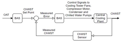
Figure 1 presents a schematic of the general principle of the CHWST reset control feedback loop. When the facility needs cooling, but the OAT is not extremely high, the building automation system (BAS) raises the CHWST temperature setpoint. The CHWST temperature sensor provides the feedback signal; based on the measured error, the BMS coordinates the central chilled water plant components (e.g., cooling tower, condenser and chilled water pumps, chiller compressor) to moderate the CHWST to meet the new setpoint.
Algorithm for the Sequence of Operation
The general CHWST reset algorithm is described in the ASHRAE handbook, “2019 ASHRAE HVAC – Applications.”1 The algorithm is implemented differently depending on the input control variable: OAT, cooling coil valve position, or chilled water return temperature.
Outdoor Air Temperature Reset
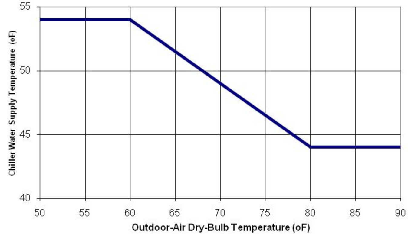
The general algorithm employed when OAT is the input variable is depicted in Figure 2. The proportional control during moderate temperatures (in this case between 60°F and 80°F) is set by the commissioning agent and generally aligns with the supply air temperature reset for the AHUs served by the central cooling plant. The upper bound of 54°F ensures sufficient dehumidification at moderate OAT and cooling loads. The lower bound of 44°F also ensures dehumidification at higher cooling loads and may reflect the lowest water temperature achievable by the chilled water plant.
Cooling Coil Valve Position
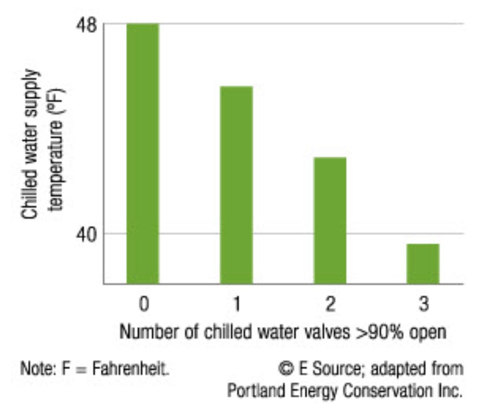
CHWST setpoint can also be modulated in proportion to the to the average position of the cooling coil valves or a Trim and Response control to step up and step down the CHWST setpoint.2 The number of chilled water valves greater than 90% open, (i.e., the number of “requests”) determines the size of the increment to be made to CHWST setpoint. One request might lead to a 1°F setpoint increase, while three requests might lead to a 3°F change. No requests lead to a Trim action, whereupon the setpoint is decreased by a fixed increment. The Trim and Response control algorithm allows for a rapid increase in CHWST and a gradual reduction, which avoids unstable cycling of the chiller system. Cooling coil valve position is the preferred input control variable (over OAT) for variable speed pumping systems (both primary and primary-secondary).
As discussed by Taylor (2012), using cooling coil valve position as the input allows for integrated control of the CHWST reset SOO with the differential pressure reset SOO, while also minimizing the risk of insufficient dehumidification by the cooling coils.2
Figure 3 shows how the algorithm works when the number of cooling coil valves is used as the input variable. The more cooling coil valves that are greater than 90% open, the lower the CHWST setpoint becomes.
Chilled Water Return Temperature
Chilled water return temperature (CHWRT) is the third possible input variable. The temperature differential (∆t) between the CHWRT and the CHWST is maintained to at least 25% of the design ∆t of the system. The use of ∆t as a control input might be found in primary-secondary chilled loop systems with constant speed primary pumps, where “low ∆t syndrome” is to be avoided (see Taylor 2002 for a detailed discussion on low ∆t).3
Energy Savings
The energy savings from CHWST reset comes from reducing the amount of electrical energy that is needed to run the central cooling plant to meet the CHWST setpoint. Figure 4 shows modeled chiller performance curves for CHWST reset.4 Note that the multiple curves represent different cooling loads; below 80°F, the curves drop (i.e., show increased efficiency).
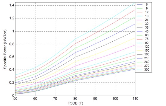
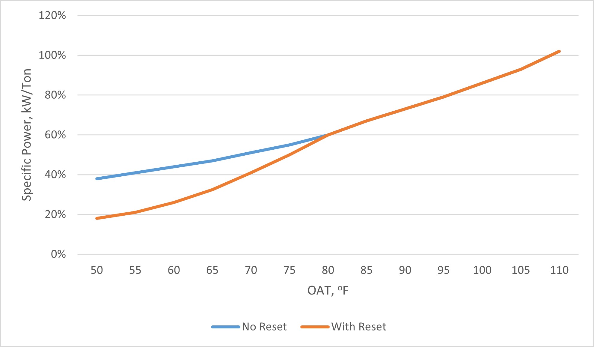
Figure 5 presents a hypothetical comparison of the performance curves with and without CHWST reset. The key period to measure the savings is when the reset comes into play, in this case when OAT < 80°F. The total annual chiller energy saved is then the number of hours at each OAT multiplied by the difference in power consumption at those OAT values. While Figure 5 represents the compressor energy saved, there will be an increase in chilled water pump energy consumption to increase flows to meet the same cooling coil loads.
Evaluation of Energy Consumption
The energy consumption of a water-cooled chilled water plant is the sum of the electrical energy of all systems associated with the plant. Key values that need to be quantified to estimate annual energy consumption are shown in Table 1.
| System Quantification | Values to be Quantified | Energy Consuming Component |
|---|---|---|
| Chilled water loop |
|
Primary CHW loop pump motor |
| Chilled water loop |
|
Secondary CHW loop pump motor (if present) |
| Water-cooled chiller |
|
Compressor motor |
| Condenser water loop | Average hourly cooling tower fan motor (kWh) | Cooling tower fan motor |
| Condenser water loop |
|
Condenser loop pump motor |
| Waterside economizer |
|
Cooling Heat Exchanger |
| Waterside economizer | Average hourly pump motor (kWh) | Pump motor (if present) |
Components to Measure and Measurement Strategy
A CHWST reset SOO has potential interactivity with the entire water-cooled chilled water plant. One key assumption when analyzing CHWST reset is that the cooling loads and operating hours are not changing between the pre- and post-retrofit periods.
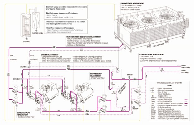
The measurement boundary includes the entire cooling plant, Figure 6 shows a representation of where to collect data in a water-cooled chilled water plant. Refer to the chilled water loop, water-cooled chiller, condenser water loop, and waterside economizer system descriptions for more details on the specific measurement points for those systems.
Interaction of CHWST Reset with other SOOs
Supply Air Temperature Reset – Since the coil water is warmer with CHWST reset, there is an increased risk of high humidity in the zones due to the reduced capacity of coils to remove moisture from the supply air.
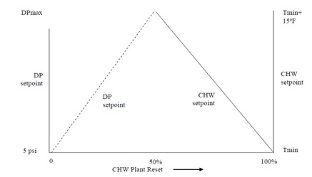
Chilled Water Pumping Differential Pressure Reset – Since differential pressure reset slows down the CHW flow and hence the heat transfer rate to the AHUs, it must be coordinated with CHWST reset. If the CHWST setpoint is raised and the flow is lowered simultaneously, it is possible that not enough heat will be removed from the building. Taylor (2012) explains that for primary variable and secondary variable chilled water loops, the two SOOs should be sequenced as shown in Figure 7: CHWST setpoint should first be increased to lower the cooling capacity; then, when the setpoint cannot be raised anymore, the differential pressure setpoint should start to be decreased. If the chilled water loop has constant speed pumps, then the sequence should be flipped: first increase the differential pressure (to reduce flow), then modulate the CHWST setpoint by staging the chillers or reducing capacity with vane guides.2
Waterside Economizing – CHWST reset impacts both full- and partial-load waterside economizing. During full-load economizing, the chiller compressor is turned off. CHWST reset still has the effect of reducing the cooling demand for the cooling towers. In addition, it extends the hours that full-load economizing is suitable. During partial-load economizing, the two SOOs work synergistically to lower the overall cooling load to the compressor and cooling tower.
Nighttime Zone Temperature Setback – Using cooling coil position or CHWRT as the input variable to CHWST reset ensures that the reset is closely coordinated with nighttime zone temperature setback. The setback suddenly changes the cooling load; cooling coil position or CHWRT would then immediately inform the algorithm to reset the CHWST setpoint. Note that using OAT as an input signal might result in a response lag.
CHWST Reset SOO Calculation Methodology
The annual energy consumption of a water-cooled chilled water plant with a CHWST reset SOO is the sum of the energy for each component system for each hour of the year. The model used must consider the hourly cooling loads and facility operations, outdoor conditions, operating parameters of the systems in the plant, and operation of associated AHU plant.
Further Reading
-
Advisor Business Energy. (2019, October 7). Energy management and information systems. Retrieved from E Source: https://esource.bizenergyadvisor.com/article/energy-management-and-information-systems
-
ASHRAE. (2019). ASHRAE Handbook Online: HVAC Applications (I-P ed.). ASHRAE. Retrieved from https://www.ashrae.org
-
ASHRAE. (2019). Standard 90.1-2019: Energy standard for buildings except low-rise residential buildings. ASHRAE.
-
Jiang, W., Winiarski, D., Katipamula, S., & Armstrong, P. (2007). Cost-Effective Integration of Efficient Low-Lift Base Load Cooling Equipment. Pacific Northwest National Laboratory.
-
New York City Department of Buildings. (2020). New York City Energy Conservation Code (NYCECC). Retrieved 2021, from Section C403.4.4: https://up.codes/viewer/new_york_city/nyc-energy-conservation-code-2020/chapter/C4/commercial-energy-efficiency#C403.4.4
-
Taylor, S. (2002). Degrading Chilled Water Plant Delta-T: Causes and Mitigation. ASHRAE Transactions, 108.
-
Taylor, S. (2012). Optimizing Design & Control of Chilled Water Plants. ASHRAE Journal, 56-74.
Footnotes
-
ASHRAE. (2019). ASHRAE Handbook Online: HVAC Applications (I-P ed.). ASHRAE. Retrieved from https://www.ashrae.org ↩︎
-
Taylor, S. (2012). Optimizing Design & Control of Chilled Water Plants. ASHRAE Journal, 56-74. ↩︎
-
Taylor, S. (2002). Degrading Chilled Water Plant Delta-T: Causes and Mitigation. ASHRAE Transactions, 108. ↩︎
-
Jiang, W., Winiarski, D., Katipamula, S., & Armstrong, P. (2007). Cost-Effective Integration of Efficient Low-Lift Base Load Cooling Equipment. Pacific Northwest National Laboratory. ↩︎