General Overview
An air-cooled chiller consists of an evaporator, a compressor, condenser fans, and an expansion valve. The system produces chilled water through the basic refrigeration cycle.
Components
Each of the various components associated with an air-cooled chiller are listed below (see Figure 1). Air-cooled chillers may be customized with a variety of high-performance components, such as variable frequency drives (VFD) on condenser fans and compressors, high efficiency compressor designs, thermostatic or electronic expansion valves, condenser coils with enhanced heat transfer characteristics, optimized condenser fan design and system airflow characteristics, and digital direct control systems that optimize the energy efficiency of the chiller.
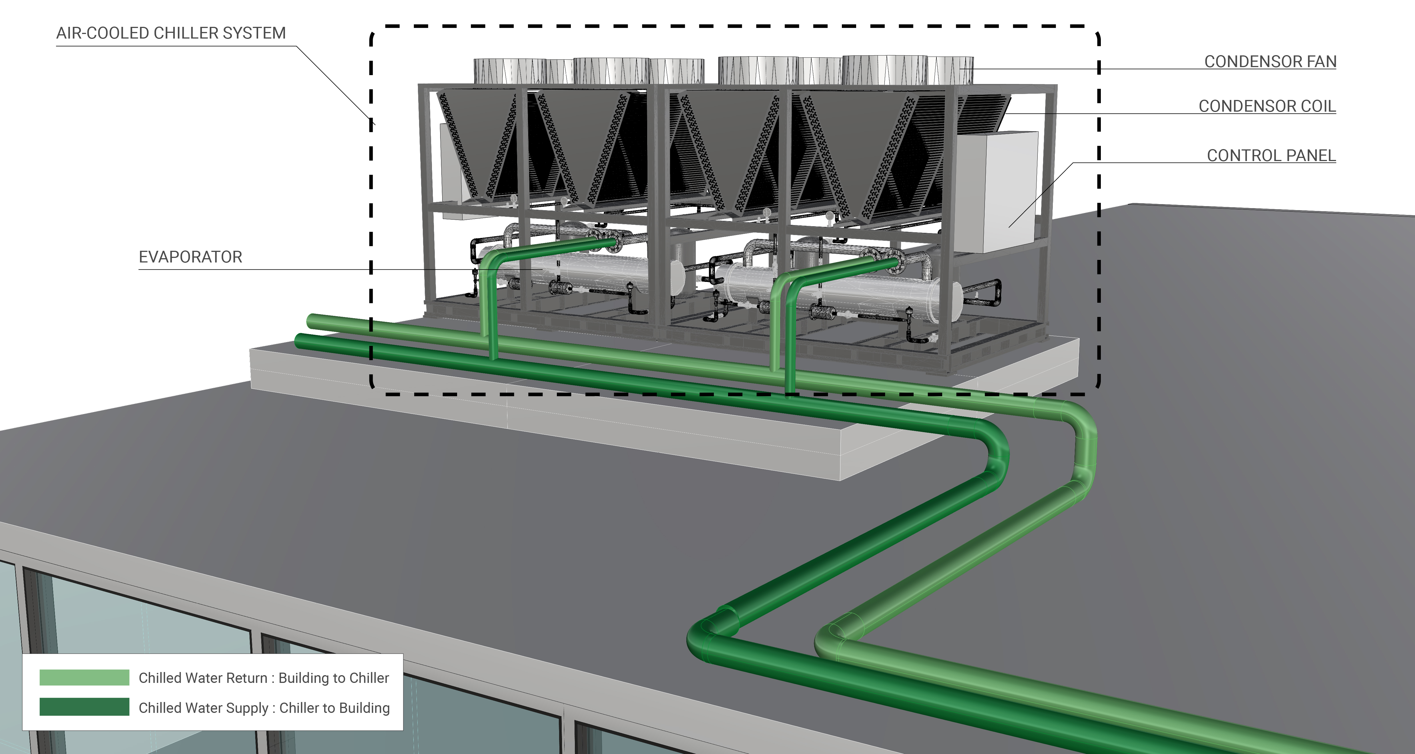
Evaporator
The evaporator transfers heat from the chilled water to the refrigerant.
Compressor
The compressor increases the temperature and pressure of the refrigerant; a chiller may have one or more compressors. Air-cooled chillers typically have screw, scroll, and reciprocating compressors.
Reciprocating compressors are among the most widely used types in this type of chiller. They consist of a cylinder and a piston that move in a reciprocating motion to compress the refrigerant. Screw compressors generate high pressure for small amounts of refrigerant vapor by compressing it between a pair of meshing screws. Scroll compressors use two interleaved scrolls that rotate simultaneously to compress refrigerant vapor within a chamber. Learn More
Condenser Fan
Condenser fans of an air-cooled chiller cool down the refrigerant by forcing airflow over the condenser coils using outdoor air.
Constant-speed, Constant-volume Condenser Fan
A constant-speed, constant-volume (CSCV) fan uses a power-driven rotating impeller to circulate air at a single speed. Learn More
Variable-speed, Variable-volume Condenser Fan
A variable-speed, variable-volume (VSVV) fan uses a power-driven rotating impeller to circulate air. Air flow rates fluctuate as required by the plant and system it serves. Learn More
Expansion Valve
The expansion valve reduces the pressure in the refrigerant, allowing it to collect heat in the evaporator.
Evaluation of Energy Consumption
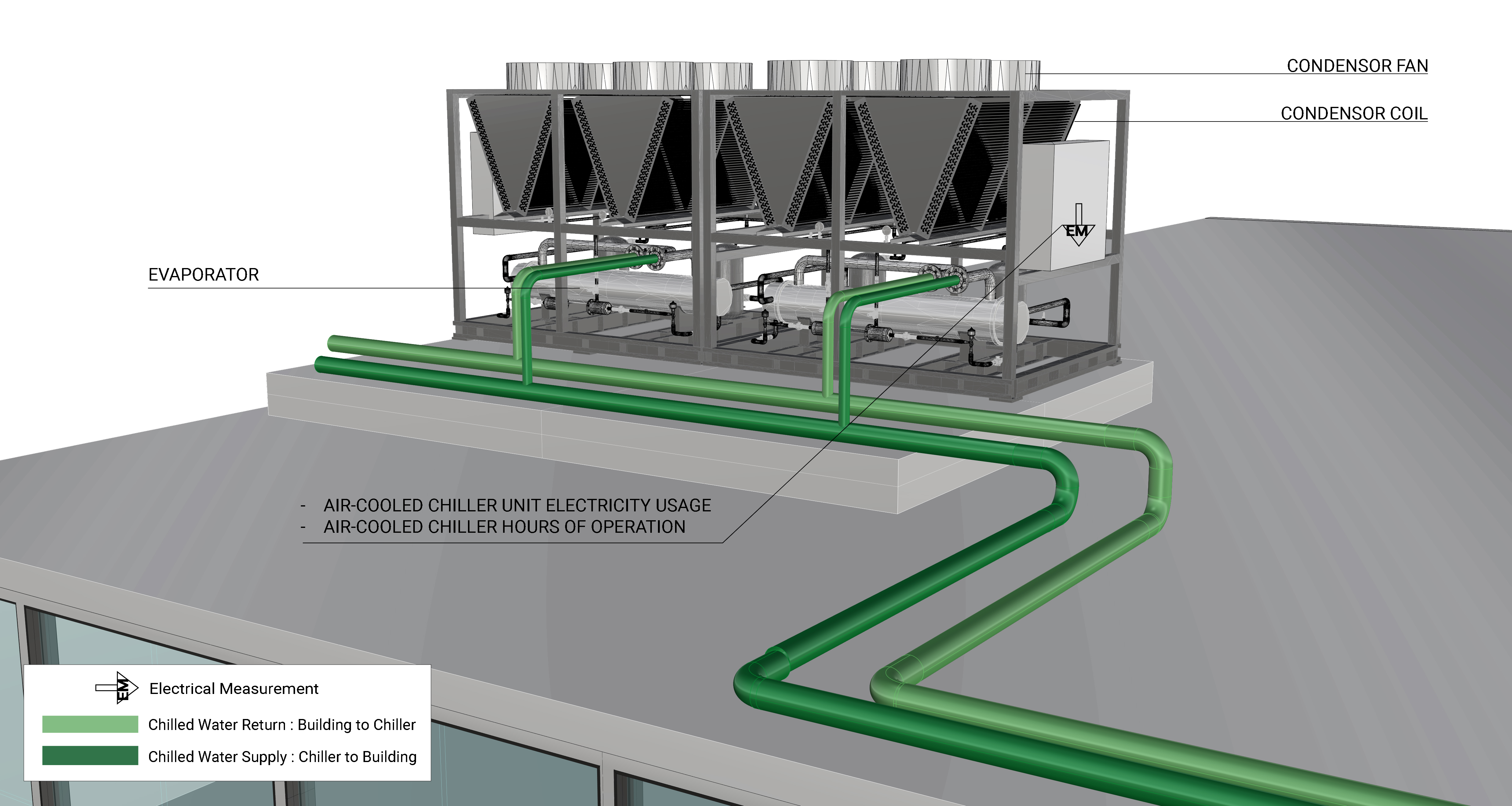
The primary energy consumption of an air-cooled chiller is the electricity used for the compressor motor and condenser fan motors. The thermal energy rejected by the chiller to the outdoors can also be measured to evaluate the overall performance of the chiller. These two values can be expressed as kilowatts of power consumed per ton of cooling provided (kW/ton). Table 1 provides a summary of the components measurements and values needed to quantify the annual energy consumption and operating characteristics of an air-cooled chiller.
| System Quantification | Values to be Quantified | Energy Consuming Component | Measurements |
|---|---|---|---|
| Air-cooled chiller electricity usage (kWh) |
|
|
|
| Cooling load on building/Heat rejected to the outdoors |
|
Evaporator |
|
Measurement Locations
The measurement locations for an air-cooled chiller and chilled water pumps are shown in Figure 2.
Further Reading
-
ASHRAE (2020). 2020 ASHRAE Handbook: HVAC Systems and Equipment. Atlanta, GA: ASHRAE.
-
Gordon, J.M.; Ng, K.C. (2000). Cool thermodynamics: The engineering and physics of predictive, diagnostic and optimization methods for cooling systems. Cambridge International Science Publishing; pp. 159-177.
-
Wei, J.; Reddy, T.A. (2003). “Reevaluation of the Gordon-Ng Performance Models for Water-Cooled Chillers.” ASHRAE Transactions, Vol. 109, Part 2. Atlanta, GA: American Society of Heating, Refrigerating and Air Conditioning Engineers.