General Overview
On warmer days during the heating season, the supply air temperature to the zones from the AHU plant can be lowered (i.e., reset) to meet the more moderate heating demands. During cooling season, the temperature can be reset upwards during periods of moderate cooling demands.
The goal of Supply Air Temperature Reset (SATR) is to use less energy to meet heating and cooling demand. When Outdoor air temperature (OAT) is moderate, the rate of heating or cooling energy supplied to the zones is moderated. Besides increasing the efficiency of the heat transfer throughout the system, there is also a reduction in the likelihood of reheat calls at variable air volume (VAV) boxes during the cooling season. In addition, the SOO modulates temperature swings in the zones, thereby improving occupant comfort.
Basic Control Logic
SOOs are feedback loops that employ a combination of sensors, controllers, and actuators to impact a process and maintain a desired state. For example, a thermostat provides a signal to a controller, and the controller sends a signal to the furnace. When the temperature falls below a certain setpoint, the controller sends a signal to the furnace to fire up and to turn on the air handler to provide heated air to the conditioned space. Once the temperature reaches the desired set point, the controller sends a signal to reduce the fan speed and/or to turn off the furnace.
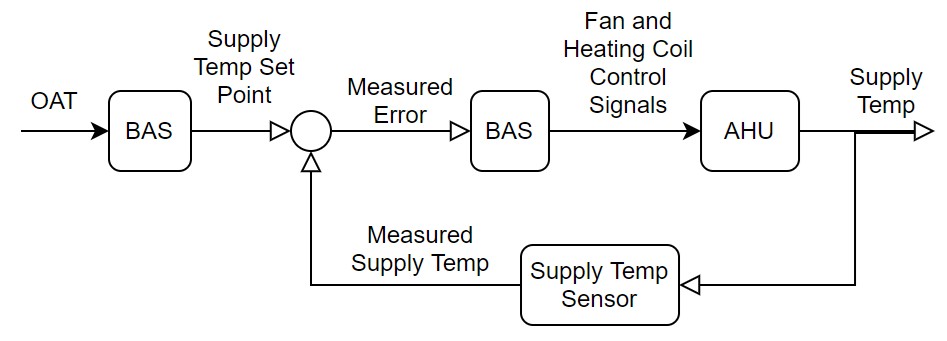
Figure 1 presents a schematic of the general principle of the supply air temperature reset (SATR) control feedback loop. If the outdoor air temperature (OAT) is moderate, and by proxy the heating, or cooling, load is not at peak condition, then the building automation system (BAS) lowers, or raises, the supply air temperature setpoint; the supply air temperature sensor provides the feedback signal. Based on the measured error, the BAS controls the supply fan and heating (or cooling) coil valve position to moderate the supply air temperature.
Algorithm for the Sequence of Operation
The algorithm is implemented differently for single-zone AHUs vs. multi-zone AHUs, and for constant volume vs. variable volume AHUs.
Single-Zone AHUs
Figure 2 shows the supply temperature reset algorithm for a single-zone AHU, which can be described as follows (from left to right):
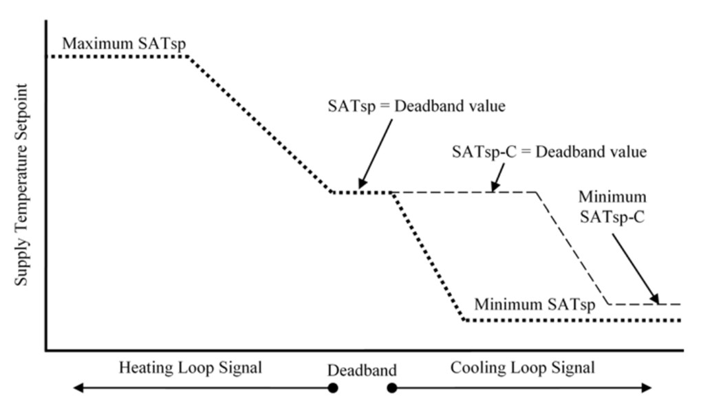
For a high heating loop signal (peak load), the supply air temperature (SAT) setpoint (SATsp) is at its maximum. As the heating load is reduced, the SATsp is reset to a lower value. The reset for the cooling loop signal shows two curves: the dotted line (labeled SATsp) is for economizer control and the dashed line (labeled SATsp-C) is for the cooling coil valve control. The two controls use the same SAT sensor. For economizing, if the measured SAT is greater than the minimum SATsp, then the outdoor air dampers will remain open. However, the measured SAT might be below the SATsp-C value at the same time, which means the cooling coil valve remains closed. The combination of the open outdoor air damper and closed cooling coil valve is the control that is needed for economizing. As the cooling loop signal increases (indicating a higher cooling load), the SATsp-C decreases. At some point, the measured SAT exceeds the setpoint, and the cooling coil valve begins to open.
For constant speed systems , the SATsp is met by changing only the heating/cooling coil valve position. For variable speed systems, the setpoint is met by changing both the heating/cooling coil valve position and the supply air flow rate. As shown in Figure 3, the control for fan speed is a function of heating/cooling loop signal, as well as OAT. The three overlapping curves for cooling show that, as OAT increases, fan speed slows down. Since warmer air holds more moisture, this logic prevents introducing too much moisture to the zones in cooling mode.
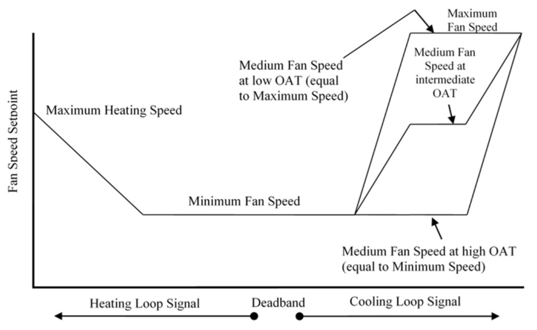
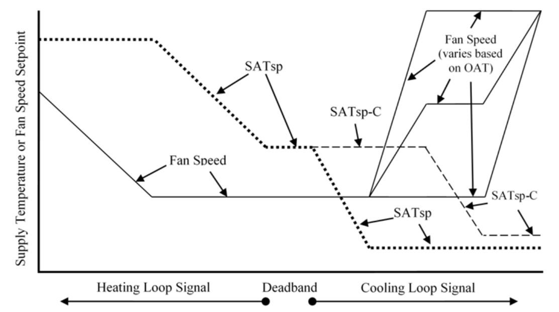
Figure 4 (which is an overlay of Figures 4 and 5) shows how fan speed is coordinated with the SATsp. Following the diagram from left to right, the highest heating demand is met by maximizing the SATsp and the fan speed. Then, as the demand is reduced, the fan speed is decreased until it reaches its minimum, at which point the SATsp is gradually decreased. After the deadband, at certain breakpoints either the fan speed is increasing while SATsp is constant, or SATsp is decreasing while fan speed is constant.
Multi-Zone VAV AHUs
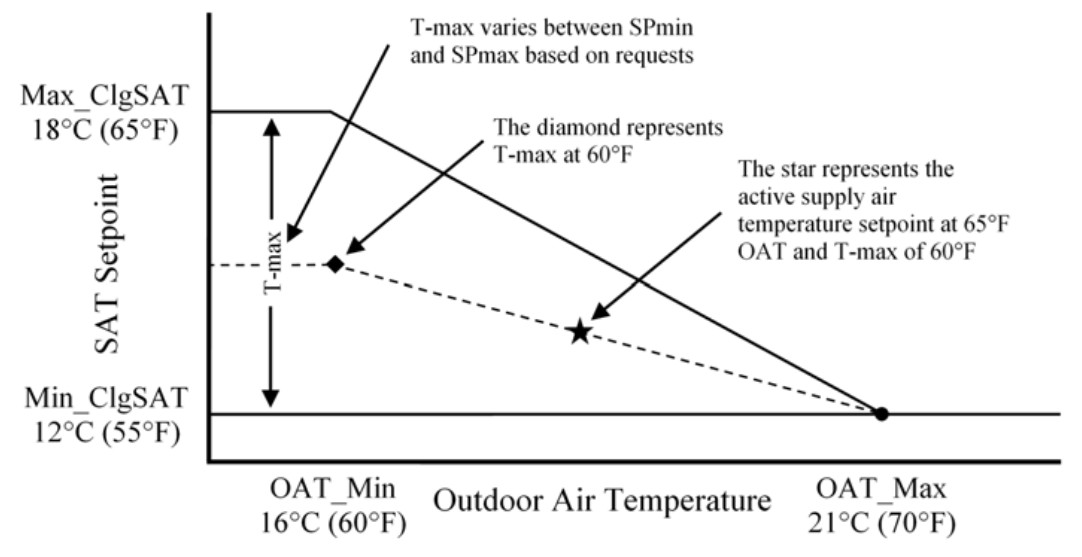
Figure 5 shows the heating season reset curve for multi-zone AHUs. The key difference between the single-zone (Figure 2) and multi-zone curves is that the slope of the curve can vary with the number of zone requests. When there are many requests from the VAV boxes, the SATR will change quickly to meet the demand. As the number of zone requests decreases, the SATR change will be less dramatic; this is known as Trim and Response control.
The supply fan speed in a multi-zone VAV AHU is set to meet static discharge pressure setpoints. Conventional control uses a constant pressure setpoint; in advanced HVAC control, the pressure is reset with the number of zone cooling SAT request according to Trim and Response logic. This is further described in the Static Pressure Reset Sequence of Operation.
Data to Represent the Heating and Cooling Signal
The last item to consider on the above diagrams is the actual measured data that represents the heating and cooling loop signal on the x-axis. The engineering literature (Trane 2016,1 PNNL 2012,2 Davis 20163) lists the following options:
-
Outdoor air temperature – The most implemented loop signal is OAT, due to the reliability of temperature sensors and the ease of commissioning the algorithm. High indoor humidity during cooling season, however, is a risk of using OAT. When the supply temperature setpoint is modulated, the cooling coil will be modulated, which may result in insufficient dehumidification. Using wet-bulb temperature as the loop signal would avoid this issue, but humidity sensors are not generally reliable.
-
Zone temperature demand – Zone temperature demand is the difference between measured zone temperature and zone temperature setpoint. If the trend of zone demand is moderate (i.e., not varying dramatically) the BAS will modulate the supply temperature setpoint. For a multi-zone AHU, a weighted average of the zone demands may be used. The commissioning agent might lower the weight for a “problem” zone that keeps calling for cooling/heating; or, they might raise the weight based on the size, use or location (e.g., interior vs. perimeter) of a zone.
-
Zone VAV box damper position – This loop signal is used less frequently. If the damper is nearly closed, the demand is low, and vice versa. Again, for a multi-zone AHU, a weighted average across the zones may be used.
-
Return air temperature – If the return air temperature is too high (or too low, for heating), then the zone cooling demand is high and the setpoint should be raised (or lowered, for heating).
-
Number of zone reheat calls – For a multi-zone AHU during cooling season, the supply air temperature setpoint can be raised if many zones are calling for reheat.
-
Combination of the above – PNNL (2012) recommends using zone demand first (zone temperature, damper position, or reheat calls), followed by return air temperature, then OAT.
The measurement section of this guide discusses the measurement of these data points.
Evaluation of Energy Consumption
The avoided energy from SATR comes from reducing the amount of thermal energy needed by the heating and cooling coils to condition mixed air, and by reducing the electrical power needed to run the AHU fans.
The total energy in the mixed air is the latent heat carried by the air’s moisture and the sensible heat as measured by the dry-bulb temperature. During cooling season, the cooling coils remove latent heat (through dehumidification) along with sensible heat. During heating season, it is assumed that only sensible heat is added by the heating coils and changes in latent heat are ignored. Changes to sensible heat are proportional to the product of air flow rate and temperature change. However, changes to latent heat are proportional to the product of air flow rate and water content change, which itself is a function of change in humidity and change in temperature.
SATR reduces these temperature changes. As was shown in Figure 2, the SATsp is modulated with demand. In the absence of SATR (i.e., the pre-retrofit condition) the curve would appear as a three-part step curve: 1) a heating season setpoint; 2) a deadband setpoint; and 3) a cooling season setpoint. The difference in the curves, and therefore the energy savings, is greatest at moderate demand, which is where facilities operate most during the year.
The change in fan energy from SATR depends on whether the AHU is a constant volume or variable volume system. For a constant volume system, the fan operation is the same with and without the SOO.
For variable volume systems with a single-zone (as seen with Figure 4), fan speed is coordinated with SATsp. Without SATR, the fan speed curve would have three parts: 1) a negatively sloped curve for heating loop signals; 2) a deadband minimum speed to meet ventilation requirements; and 3) a positively sloped curve for cooling loop signals.
| System | Values to be Quantified | Energy Consuming Component |
|---|---|---|
| AHU |
|
Supply air fan and motor |
| AHU |
|
Heating heat exchanger |
| AHU |
|
Cooling heat exchanger |
Components to Measure and Measurement Strategy
The measurement locations for a SATR SOO are shown in Figure 6.
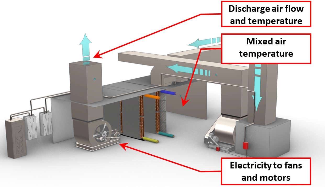
The SATR SOO measurement boundary includes the mixed air, discharge air, heat exchangers, power supply for the supply fan motor, and the supply fan and motor.
Interaction of SATR with other SOOs
The supply air temperature reset SOO has potential interactivity with other SOOs listed below. Cumulatively, these may also interact with the overall heating plant and water- or air-cooled chilled water plant.
Economizing and Direct Control Ventilation (DCV) – These two SOOs both control the outdoor air damper, which in turn impacts the temperature and relative humidity of the mixed air. The mixed air is then conditioned to meet the SATsp. While SATR operates independently of the outside air damper position, economizing and DCV will impact the amount of energy used to condition the air. Therefore, economizing and DCV should be applied consistently between pre- and post-retrofit conditions to properly evaluate the impact of SATR.
Static Pressure Reset – SATR and static pressure reset have a complicated interaction. Both SOOs seek to modulate when demand is moderate. As the SATsp is modulated, the zones may call for greater air flow, which means higher pressure is generated, contrary to the goal of the static pressure reset algorithm. Taylor (2016) points out that the two algorithms operate on different time scales, and therefore concerns that they work against each other are misplaced.1 SAT is reset gradually through the day, while static pressure resets may happen frequently within an hour. Nevertheless, static pressure reset should be applied consistently between pre- and post-retrofit conditions.
SATR SOO Calculation Methodology
One underlying assumption regarding this SOO is that the heating and cooling loads for the zones being served do not change during the pre- and post-retrofit periods and are correlated to OAT and hours of operation. The hourly electrical energy and thermal energy associated with heating or cooling the air is summed by OAT and coincident operating hours, and a regression model is developed. This is used with climate normal year data to develop an estimate of annual fan and motor electrical energy consumption and annual heating and cooling consumption.
Further Reading
-
ASHRAE. (2018). ASHRAE Guideline 36-2018: High Performance Sequences of Operation for HVAC Systems. Atlanta, GA: ASHRAE.
-
Davis, G. (2016, August 15). HVAC codes and standards: cooling and energy efficiency. Retrieved January 15, 2021, from Consulting-Specifying Engineer:https://www.csemag.com/articles/hvac-codes-and-standards-cooling-and-energy-efficiency/
-
New York City Department of Buildings. (2020). New York City Energy Conservation Code (NYCECC). Retrieved 2021, from Section C403.6.5: https://up.codes/viewer/new_york_city/nyc-energy-conservation-code-2020/chapter/C4/commercial-energy-efficiency#C403.6.5
-
Pacific Northwest National Laboratory. (2012).Large Commercial Buildings: Re-tuning for Efficiency-Air Handling Units: Pre-Re-Tuning and Trending and Re-Tuning.Retrieved January 2021, from https://buildingretuning.pnnl.gov/documents/chapters/ch5_air_handling.pdf
-
Trane. (2016). Multiple-zone VAV systems - Finding the Right Balance for VAV Energy Savings. Trane Engineers Newsletter, 45(3).
Footnotes
-
Trane (2016). Multiple-zone VAV systems - Finding the Right Balance for VAV Energy Savings. Trane Engineers Newsletter, 45(3). ↩︎
-
Pacific Northwest National Laboratory (2012). Large Commercial Buildings: Re-tuning for Efficiency - Air Handling Units: Pre-Re-Tuning and Trending and Re-Tuning. Retrieved January 2021, from https://buildingretuning.pnnl.gov/documents/chapters/ch5_air_handling.pdf ↩︎
-
Davis, G. (2016, August 15). HVAC codes and standards: cooling and energy efficiency. Retrieved January 15, 2021, from Consulting-Specifying Engineer: https://www.csemag.com/articles/hvac-codes-and-standards-cooling-and-energy-efficiency/ ↩︎