General Overview
An electrical distribution system is made up of switchgear and panelboards connected by wires. Switchgear is used to disaggregate the power coming from the utility grid to serve various aggregate loads in a facility, such as lights, motors, receptacle circuits, or miscellaneous equipment. A panelboard is used as the final disconnect and protection point for individual circuits in a space. A lighting panelboard is connected to the light fixture system in one or more spaces, typically on a single floor of a facility, or the outdoor light fixture system. Panelboards may either be dedicated to the lighting system or “mixed”, serving both lighting loads and other circuits.
Components
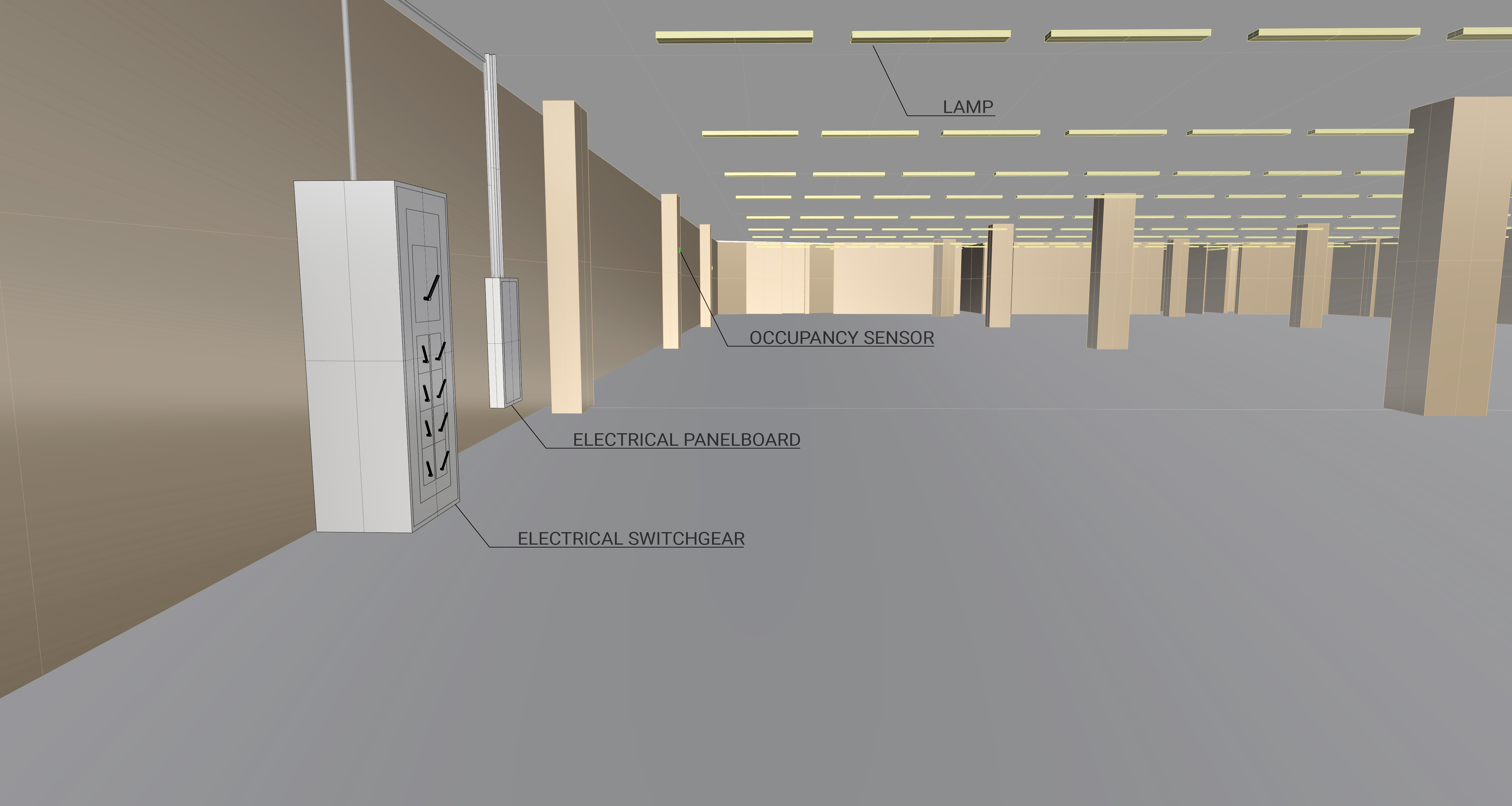
Figure 1 shows the main components associated with the electrical distribution system: switchgear and panelboard.
Switchgear
Switchgear is an assembly that contains circuit breakers, fuses, and other accessories to interrupt current flow and protect electrical equipment and occupants. The electricity delivered by a utility company is passed through a step-down transformer and then to a switchgear as the first layer of protection in a facility. Then, electricity is distributed among other assemblies, such as a secondary switchgear or panelboards. The configuration of primary and secondary switchgears is dependent on the facility. Not all facilities have secondary switchgear.
Dedicated Panelboard
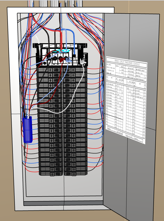
A dedicated electrical panelboard supplies electricity only to the light fixture system. Figure 2 shows a dedicated panelboard without a panel cover to show how the electrical wiring is distributed. The electricity from the primary or secondary switchgear enters from the top (or bottom) of the panelboard, and then splits across all of the branch circuits.
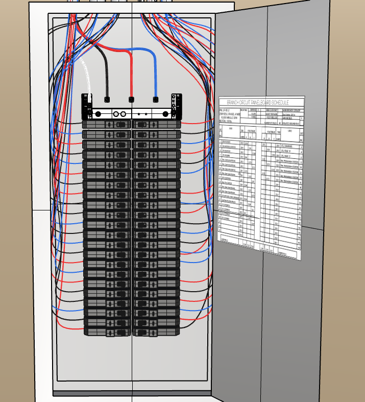
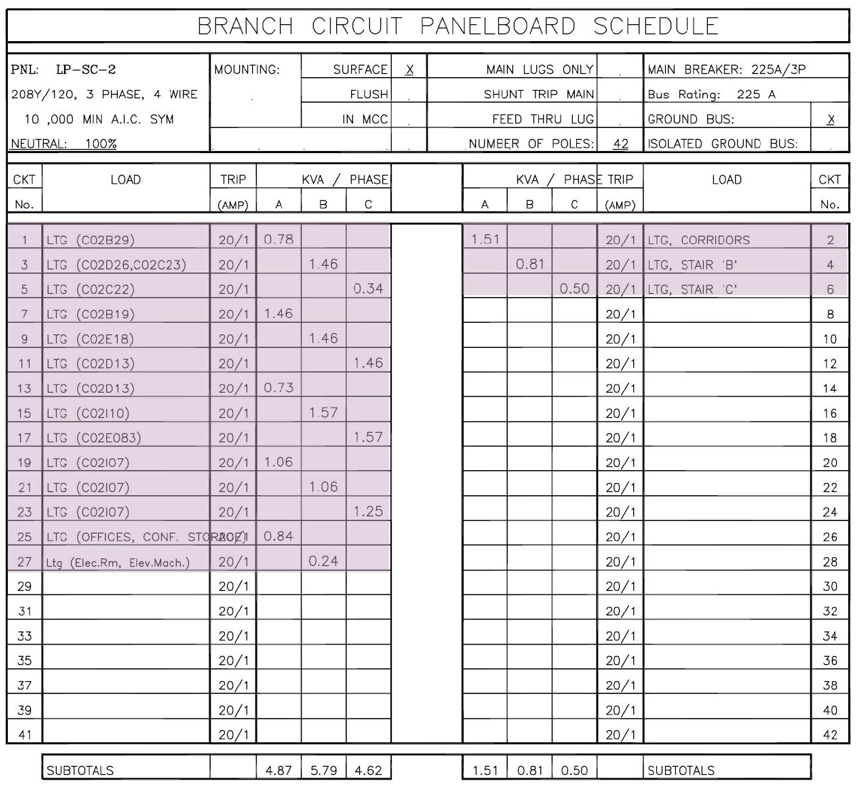
Figure 3 is an example of a schedule of circuits on a dedicated panelboard. The schedule typically describes the type of load (e.g., lights) and the space that is served by the breaker. There is no standard naming convention for circuits.
Mixed Panelboard
A Mixed electrical panelboard supplies electricity to the lighting fixture system and other loads (typically receptacle circuits). Mixed panelboards typically exist in small or older facilities. The electricity from the primary or secondary switchgear enters from the top or bottom of the panelboard and then splits across all of the branch circuits. The interior of a mixed panelboard looks similar to Figure 2, but the panel schedule highlights a collection of different loads as shown in Figure 4.
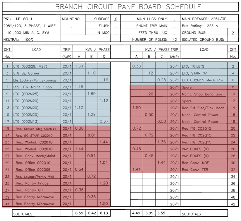
Figure 4: Example of a mixed panelboard schedule. Lighting fixtures highlighted in blue, and other electrical loads highlighted in red.
Evaluation of Energy Consumption
The electrical distribution system does not consume electricity, but it can be a useful point by which to measure the electrical energy associated with the Lighting Plant.
| System Quantification | Values to be Quantified | Energy Consuming Component | Measurements |
|---|---|---|---|
| Lighting fixture system electricity consumption (kWh) |
|
Light fixtures and automatic controls (if applicable). |
|
Measurement Locations
Figures 5 and 6 show typical measurement locations in an electrical distribution system.
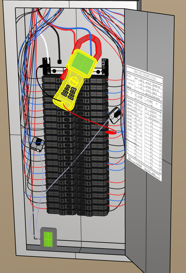
Measurement locations in the electrical distribution system are at the conductors in the panelboard or switchgear. To measure a lighting plant, the best practice is to capture as much of the lighting plant in a single measurement as possible. Measuring at switchgear may be appropriate if all lighting panelboards are dedicated and connected to it, but only the distribution line that supplies electricity to lighting should be measured. Alternatively, a sample of panelboards and/or circuits can be measured, but a sampling plan must be considered. For more information on sampling, please refer to Bonneville Power Administration’s guide on sampling.
Further Reading
-
Consulting-Specifying Engineer (20). “Back to Basics: Switchgear, Transformers and UPSs.”. https://www.csemag.com/articles/back-to-basics-switchgear-transformers-and-upss/; accessed May 24, 2022.
-
Bonneville Power Administration (July 2018). “Sampling for M&V: Reference Guide.”
-
EE Richman (February 2016). PNNL-SA-25222. “Measurement and Verification of Energy Savings and Performance from Advantage Lighting Controls” Richland, WA: Pacific Northwest National Laboratory.